Apparatus, systems, and methods for the fixation or fusion of bone

a technology of fixation or fusion, applied in the field of bone fixation or fusion, can solve the problems of too much movement between two vertebrae, affecting the ability of each spinal segment to bear weight, so as to speed up the fusion and/or stabilization process, reduce the risk of fracture, and reduce the effect of incision

Inactive Publication Date: 2018-08-16
SI BONE
View PDF3 Cites 20 Cited by
  • Summary
  • Abstract
  • Description
  • Claims
  • Application Information

AI Technical Summary

Benefits of technology

[0023]Embodiments of the invention provide bone fixation / fusion systems, devices, and related methods for stabilizing adjacent bone segments in a minimally invasive manner. The adjacent bone segments can comprise parts of the same bone that have been fractured, or two or more individual bones separated by a space or joint. As used herein, “bone segments” or “adjacent bone regions” refer to either situation, i.e., a fracture line in a single bone (which the devices serve to fixate), or a space or joint between different bone segments (which the devices serve to arthrodese or fuse). The devices can therefore serve to perform a fixation function between two or more individual bones, or a fusion function between two or more parts of the same bone, or both functions.
[0026]Accordingly, another aspect of the invention provides a method for the fusion of the sacral-iliac joint between an iliac and a sacrum. The method comprises creating an insertion path through the ilium, through the sacral-iliac joint, and into the sacrum. The method includes providing an anchor body sized and configured to be introduced through the insertion path laterally into the ilium and sacrum. The anchor body has a distal end sized and configured to be located in an interior region of the sacrum; a proximal end sized and configured to be located outside an exterior region of the iliac; and an intermediate region sized and configured to span the sacral-iliac joint. The method includes providing an elongated implant structure sized and configured to be passed over the anchor body to span the sacral-iliac joint between the iliac and sacrum. The elongated implant structure includes an exterior surface region treated to provide bony in-growth or through-growth along the implant structure. The method includes introducing the anchor body through the insertion path from the ilium, through the sacral-iliac joint, and into the sacrum. The method includes anchoring the distal end of the anchor body in the interior region of the sacrum. The method includes passing the elongated implant structure over the anchor body to span the sacral-iliac joint between the ilium and sacrum, and anchoring the proximal end of the anchor body to an exterior region of the ilium, which, in concert with the anchored distal end, places the anchor body in compression to compress and fixate the sacral-iliac joint. The bony in-growth or through-growth region of the implant structure accelerates the fixation or fusion of the sacral-iliac joint held in compression and fixated by the anchor body.
[0027]Embodiments of the invention provide apparatus, systems, and methods for the fusion and / or stabilization of the lumbar spine. The apparatus, systems, and methods include one or more elongated, stem-like implant structures sized and configured for the fusion or stabilization of adjacent bone structures in the lumbar region of the spine, either across the intervertebral disc or across one or more facet joints. Each implant structure includes a region formed along at least a portion of its length to promote bony in-growth onto or into surface of the structure and / or bony growth entirely through all or a portion of the structure. The bony in-growth or through-growth region along the surface of the implant structure accelerates bony in-growth or through-growth onto, into, or through the implant structure 20. The implant structure therefore provides extra-articular / intra osseous fixation, when bone grows in and around the bony in-growth or through-growth region. Bony in-growth or through-growth onto, into, or through the implant structure helps speed up the fusion and / or stabilization process of the adjacent bone regions fixated by the implant structure.
[0028]The assemblies of one or more implant structures make possible the achievement of diverse interventions involving the fusion and / or stabilization of lumbar and sacral vertebra in a non-invasive manner, with minimal incision, and without the necessitating the removing the intervertebral disc. The representative lumbar spine interventions, which can be performed on adults or children, include, but are not limited to, lumbar interbody fusion; translaminar lumbar fusion; lumbar facet fusion; trans-iliac lumbar fusion; and the stabilization of a spondylolisthesis.

Problems solved by technology

Degenerative changes in the spine can adversely affect the ability of each spinal segment to bear weight, accommodate movement, and provide support.
When one segment deteriorates to the point of instability, it can lead to localized pain and difficulties.
Segmental instability allows too much movement between two vertebrae.
The excess movement of the vertebrae can cause pinching or irritation of nerve roots.
It can also cause too much pressure on the facet joints, leading to inflammation.
It can cause muscle spasms as the paraspinal muscles try to stop the spinal segment from moving too much.
The instability eventually results in faster degeneration in this area of the spine
Degenerative changes in the spine can also lead to spondylolysis and spondylolisthesis.
An untreated persistent, episodic, severely disabling back pain problem can easily ruin the active life of a patient.
However, in for severe and persistent problems that cannot be managed by these treatment options, degenerative changes in the spine may require a bone fusion surgery to stop both the associated disc and facet joint problems
In some cases the vertebrae are moved back to the normal position prior to performing the fusion, and in others the vertebrae are fused where they are after the slip, due to the increased risk of injury to the nerve with moving the vertebra back to the normal position
Like all invasive open surgical procedures, such operations on the spine risk infections and require hospitalization.
Invasive open surgical techniques involving the spine continue to be a challenging and difficult area.

Method used


Image

  • Apparatus, systems, and methods for the fixation or fusion of bone
  • Apparatus, systems, and methods for the fixation or fusion of bone
  • Apparatus, systems, and methods for the fixation or fusion of bone

Examples


Embodiment Construction

[0073]Although the disclosure hereof is detailed and exact to enable those skilled in the art to practice the invention, the physical embodiments herein disclosed merely exemplify the invention that may be embodied in other specific structure. While the preferred embodiment has been described, the details may be changed without departing from the invention, which is defined by the claims.

Part I

[0074]The following describes embodiments of the invention for use in the fixation or fusion of the SI-joint and other bone segments or joints.

[0075]I. The Compression Stem Assembly

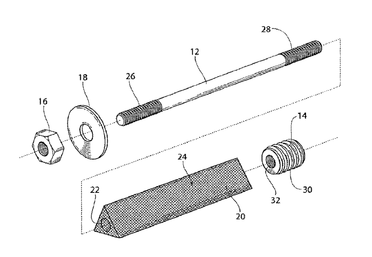
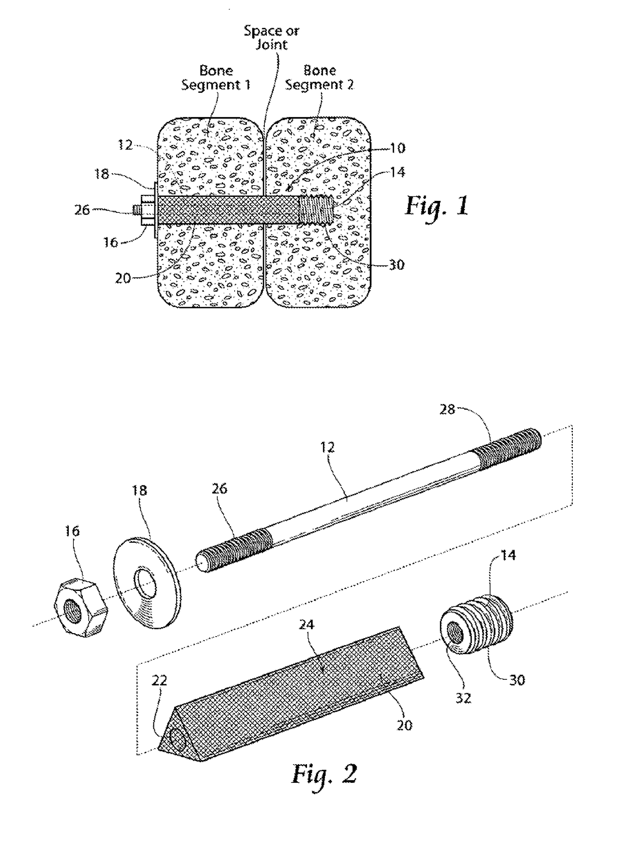
[0076]FIGS. 1 and 2 show in assembled and exploded views, respectively, a representative configuration of a compression stem assembly 10 sized and configured for the fixation of bone fractures (i.e., fixation of parts of the same bone) or for the fixation of bones which are to be fused (arthrodesed) (i.e. fixation of two or more individual bones that are adjacent and / or jointed). For the sake of shorthand, the assem...


PUM


Abstract

Assemblies of one or more implant structures make possible the achievement of diverse interventions involving the fusion and / or stabilization of the SI-joint and / or lumbar and sacral vertebra in a non-invasive manner, with minimal incision, and without the necessitating the removing the intervertebral disc. The representative lumbar spine interventions, which can be performed on adults or children, include, but are not limited to, SI-joint fusion or fixation; lumbar interbody fusion; translaminar lumbar fusion; lumbar facet fusion; trans-iliac lumbar fusion; and the stabilization of a spondylolisthesis.

Description

CROSS REFERENCE TO RELATED APPLICATIONS[0001]This application is a continuation of U.S. patent application Ser. No. 15 / 195,955, filed Jun. 28, 2016, titled “APPARATUS, SYSTEMS, AND METHODS FOR THE FIXATION OR FUSION OF BONE”, which is a continuation-in-part of U.S. patent application Ser. No. 13 / 858,814, filed Apr. 8, 2013, titled “APPARATUS, SYSTEMS, AND METHODS FOR ACHIEVING TRANS-ILIAC LUMBAR FUSION,” now U.S. Pat. No. 9,375,323, which is a continuation of U.S. patent application Ser. No. 12 / 960,831, filed Dec. 6, 2010, titled “APPARATUS, SYSTEMS, AND METHODS FOR ACHIEVING TRANS-ILIAC LUMBAR FUSION,” now U.S. Pat. No. 8,414,648, which is a continuation-in-part of U.S. patent application Ser. No. 11 / 136,141, filed May 24, 2005, titled “SYSTEMS AND METHODS FOR THE FIXATION OR FUSION OF BONE,” now U.S. Pat. No. 7,922,765, which is a continuation-in-part of U.S. patent application Ser. No. 10 / 914,629, filed Aug. 9, 2004, titled “SYSTEMS AND METHODS FOR THE FIXATION OR FUSION OF BONE,...

Claims


Application Information

Patent Timeline
Patent Type & Authority Applications(United States)
IPC IPC(8): A61F2/44A61B17/16
CPCA61B17/1615A61F2/447A61F2310/00179A61F2310/00131A61F2310/0097A61F2310/00029A61F2310/00023A61F2310/00017A61F2230/0069A61F2230/0058A61F2230/0023A61F2220/0025A61F2210/0004A61F2002/448A61F2002/4238A61F2002/30841A61F2002/30787A61F2002/30785A61F2002/30777A61F2002/30622A61F2002/30604A61F2002/30576A61F2002/30405A61F2002/30235A61F2002/30179A61F2002/30156A61F2002/3085A61F2002/3082A61F2002/30062A61F2002/3023A61F2002/305A61F2/4465A61F2/30767A61F2/28A61F2/0077A61B17/864A61B17/1757A61B17/1637A61F2/4455A61F2/446A61B17/8685A61B17/866A61B17/7055A61B17/68A61B17/1671A61B17/1664A61B17/1659A61F2310/00796A61F2310/00329A61F2002/30995A61B2017/00889A61B17/7058A61B17/1604A61B17/8625A61B17/844
Inventor REILEY, MARK A.LERMAN, JUSTINMAULDIN, RICHARD G.
Owner SI BONE
Why Eureka
Try Eureka