Electronic brake system and control method thereof

Active Publication Date: 2018-08-16
HL MANDO CORP
View PDF7 Cites 12 Cited by
  • Summary
  • Abstract
  • Description
  • Claims
  • Application Information

AI Technical Summary

Benefits of technology

The present disclosure aims to provide an electronic brake system and a control method that can replicate the feel of a brake pedal when a driver steps on it, which improves the reliability of the vehicle. Additionally, it also aims to provide a system that can reduce the anxiety that drivers experience during braking.

Problems solved by technology

However, a conventional electronic brake system has a limitation in realizing current pedal feel of a brake pedal during braking.
For example, when a conventional electronic brake system is applied to a vehicle in at least one form among an anti-lock brake system (ABS) configured to prevent wheels from slipping during braking, a brake traction control system (BTCS) configured to prevent drive wheels from slipping when a vehicle is unintentionally or intentionally accelerated, and an electronic stability control (ESC) system configured to stably maintain a traveling state of a vehicle by controlling a brake hydraulic pressure in combination with ABS and BTCS, there is a limitation in the efficient generation of a pedal feel having a vibration feel corresponding to at least one of ABS, BTCS, and ESC during braking.

Method used


Image

  • Electronic brake system and control method thereof
  • Electronic brake system and control method thereof
  • Electronic brake system and control method thereof

Examples


Embodiment Construction

[0030]Hereinafter, embodiments of the present disclosure will be described in detail with reference to the accompanying drawings. The embodiments to be described below are provided to fully convey the spirit of the present disclosure to those skilled in the art. The present disclosure is not limited to the embodiments disclosed herein and may be implemented in other forms. In the drawings, some portions not related to the description will be omitted and not be shown to clearly describe the present disclosure, and sizes of components may be somewhat exaggerated to facilitate understanding.

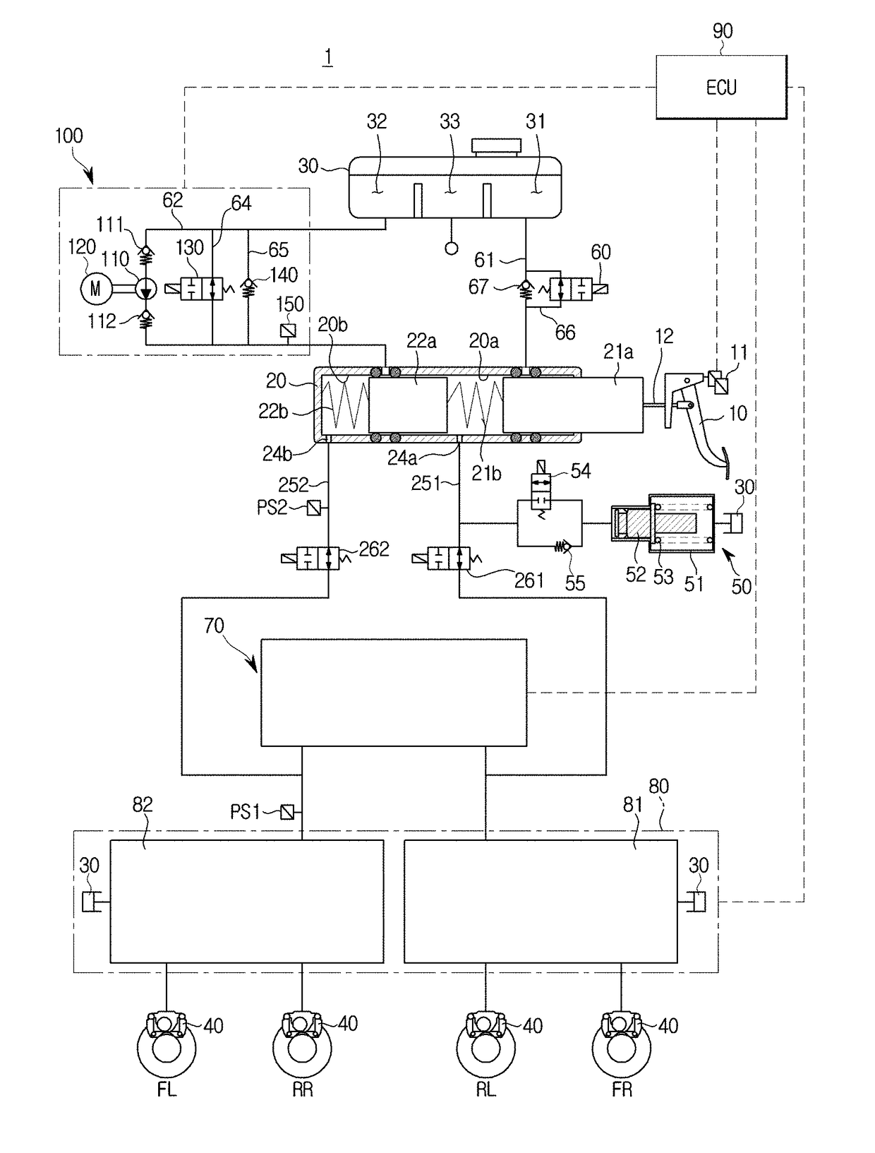
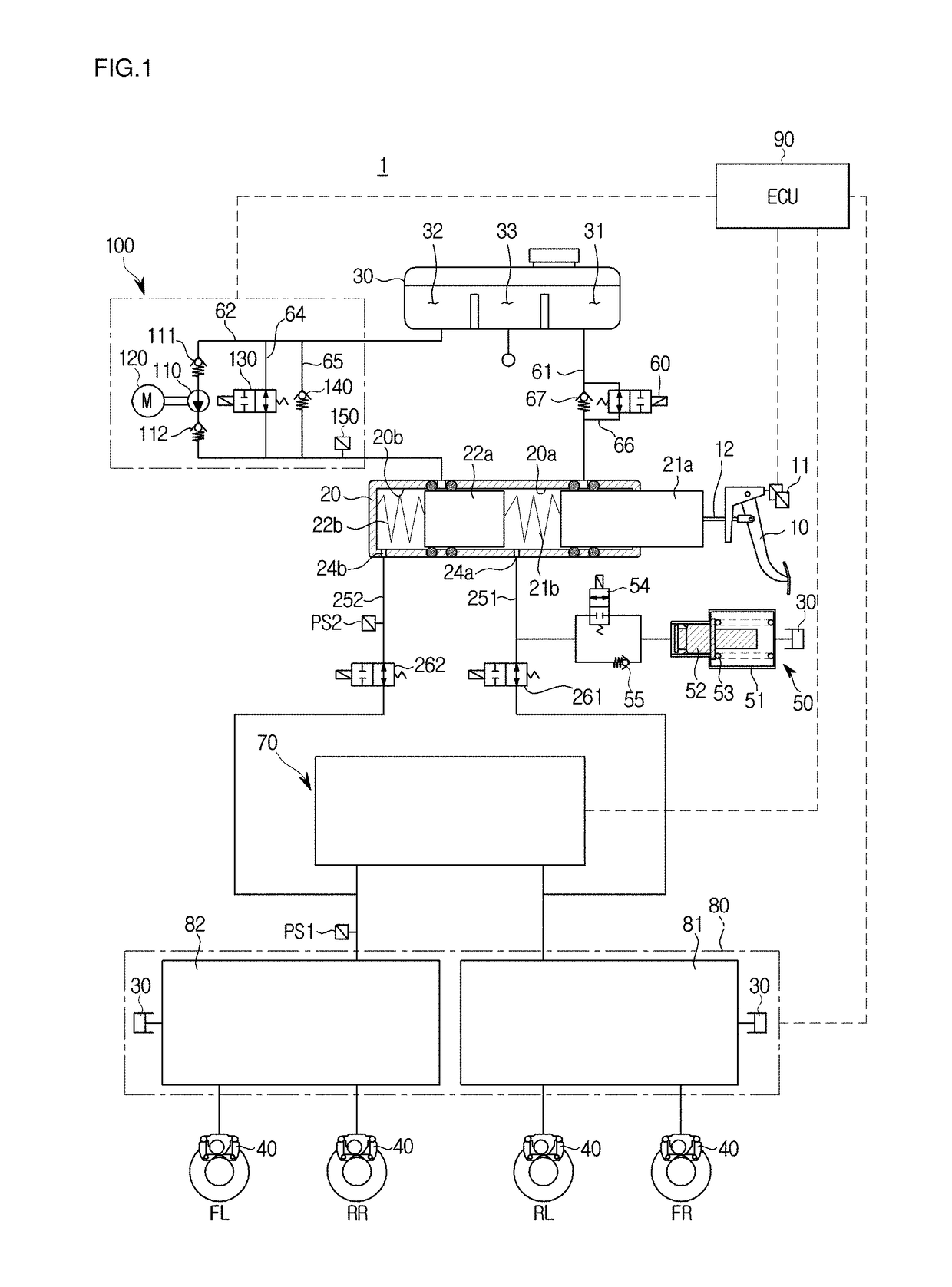
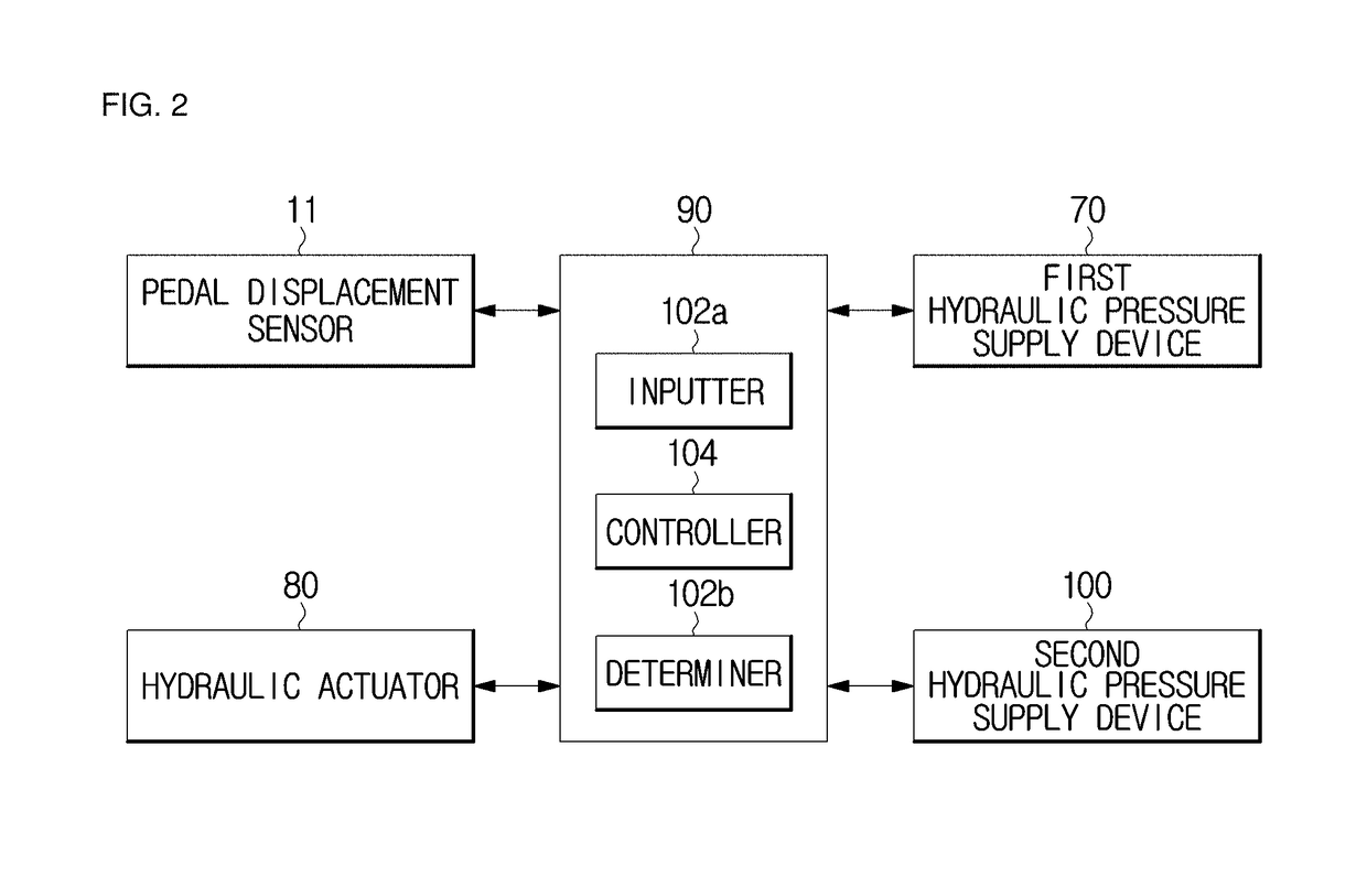
[0031]FIG. 1 is a hydraulic pressure circuit diagram illustrating a non-braking state of an electronic brake system according to one embodiment of the present disclosure, FIG. 2 is a block diagram illustrating the electronic brake system according to one embodiment of the present disclosure, and FIG. 3 is a graph illustrating feel of a brake pedal when a second hydraulic pressure supply device of th...


PUM


Abstract

Disclosed herein are an electronic brake system and a control method thereof. The electronic brake system includes a master cylinder connected to a reservoir storing oil, including a master chamber and a master piston provided at the master chamber, and configured to discharge the oil according to pedal effort of a brake pedal, a sensor configured to measure a displacement of the brake pedal, a pedal simulator configured to provide a reaction force according to pedal effort of the brake pedal and including a simulator chamber connected to the master cylinder to accommodate the oil, a hydraulic actuator provided between the master cylinder and a wheel cylinder and configured to control a hydraulic pressure flow delivered to the wheel cylinder, a first hydraulic pressure supply device operated by an electrical signal which is output by corresponding to the displacement of the brake pedal, and configured to supply a hydraulic pressure to the hydraulic actuator, and a second hydraulic pressure supply device provided between the reservoir and the master cylinder and configured to provide a vibration pedal feel to the brake pedal.

Description

CROSS-REFERENCE TO RELATED APPLICATION[0001]This application is based on and claims priority under 35 U.S.C. § 119 to Korean Patent Application No. 10-2017-0020649, filed on Feb. 15, 2017 and Korean Patent Application No. 10-2018-0018179, filed on Feb. 14, 2018, in the Korean Intellectual Property Office, the disclosure of which are incorporated by reference herein in its entirety.BACKGROUND1. Field[0002]The present disclosure relates to an electronic brake system and a control method thereof.2. Description of the Related Art[0003]Generally, a conventional electronic brake system is applied to a vehicle to perform braking efficiently and stably.[0004]A conventional electronic brake system is divided into a portion configured to generate a pedal effort for a driver and a portion configured to generate a braking force at a wheel.[0005]However, a conventional electronic brake system has a limitation in realizing current pedal feel of a brake pedal during braking.[0006]For example, when...

Claims


Application Information

Patent Timeline
IPC IPC(8): B60T8/40B60T7/04
CPCB60T8/4086B60T7/042B60T2220/04B60T8/4081
Inventor SON, JOO-HEECHOI, SEONG-HO
Owner HL MANDO CORP
Why Eureka
Try Eureka