

Fuel cell vehicle
a fuel cell and vehicle technology, applied in the direction of battery/fuel cell control arrangement, vehicle sub-unit features, electric devices, etc., can solve the problems of collision damage of high-voltage devices at the time of high-voltage device collision, the arrangement for curbing the rear high-voltage device damage has not been sufficiently studied, and the damage of high-voltage devices may be damaged, etc., to achieve the effect of increasing the rigidity and strength of the cas
- Summary
- Abstract
- Description
- Claims
- Application Information
AI Technical Summary
Benefits of technology
Problems solved by technology
Method used
Image

Examples
first embodiment
A. FIRST EMBODIMENT
A-1 Overall Configuration of Fuel Cell Vehicle
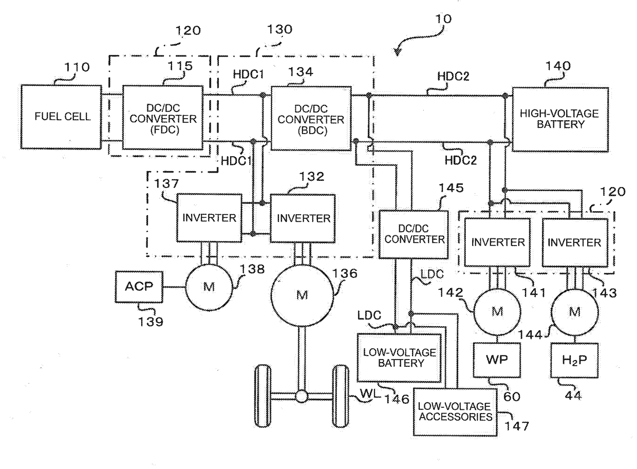
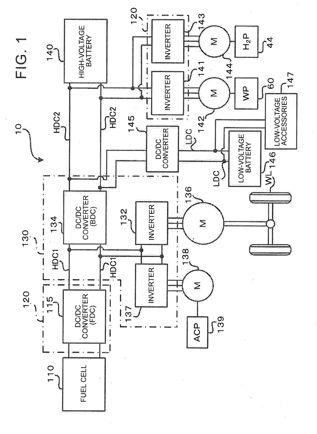
[0038]FIG. 1 shows the general configuration of a fuel cell vehicle 10 as a first embodiment of the disclosure. While this embodiment is characterized in the arrangement of respective parts of the fuel cell vehicle 10 shown in FIG. 1, the configuration of the whole system installed on the fuel cell vehicle 10 will be initially described.
[0039]The fuel cell vehicle 10 includes a fuel cell 110, DC / DC converter (which may be referred to as “FDC”) 115, high-voltage battery 140, DC / DC converter (which may be referred to as “BDC”) 134, drive motor 136, air compressor (which may be abbreviated to “ACP”) 139, water pump (which may be abbreviated to “WP”) 60, and a hydrogen pump (which may be abbreviated to “H2P”) 44. The fuel cell vehicle 10 travels while driving the drive motor 136 using electric power (electric energy), as a drive source, generated by the fuel cell 110, and the high-voltage battery 140 as a secondary battery...
second embodiment
B. SECOND EMBODIMENT
[0083]The plan view of FIG. 7 similar to FIG. 3 schematically shows a condition within a front compartment of a fuel cell vehicle 210 of a second embodiment. The fuel cell vehicle 210 of the second embodiment has substantially the same configuration as the fuel cell vehicle 10 of the first embodiment, except that the vehicle 210 includes a first high-voltage unit 220, in place of the first high-voltage unit 120. Therefore, the same reference numerals are assigned to portions or components common to the first embodiment, and detailed description of the portions or components will not be provided.
[0084]The first high-voltage unit 220 of the second embodiment has a chamfered portion 124 formed in a rear end portion of the first high-voltage unit 220 in the traveling direction, on one side (right-hand side) closer to the suspension tower 154. The chamfered portion 124 is located on the inner side of a shape formed by extending side faces of the first case 125 close t...
third embodiment
C. THIRD EMBODIMENT
[0093]The plan view of FIG. 13 similar to FIG. 3 schematically shows a condition within a front compartment of a fuel cell vehicle 310 of a third embodiment. The fuel cell vehicle 310 of the third embodiment has substantially the same configuration as the fuel cell vehicle 10 of the first embodiment, except that the vehicle 310 includes a first high-voltage unit 320, in place of the first high-voltage unit 120. Therefore, the same reference numerals are assigned to portions or components common to the first embodiment, and detailed description of the portions or components will not be provided.
[0094]The first high-voltage unit 320 of the third embodiment has a protrusion 126 that protrudes in the −Y direction, and the protrusion 126 is formed on a rear end portion of the first high-voltage unit 320 in the traveling direction, on the side (left-hand side) closer to the suspension tower 155. In this embodiment, no other high-voltage devices are placed between the pr...
PUM
 Abstract
Description
Claims
Application Information