Insertion unit support system

Inactive Publication Date: 2018-08-23
OLYMPUS CORP
View PDF0 Cites 6 Cited by
  • Summary
  • Abstract
  • Description
  • Claims
  • Application Information

AI Technical Summary

Problems solved by technology

An insertion portion (or insertion unit) of an endoscope, once inserted into a lumen, does not allow for direct visual recognition of its position or bending form.
There is therefore a concern that without advice or some assistance from an expert,

Method used


Image

  • Insertion unit support system
  • Insertion unit support system
  • Insertion unit support system

Examples


first embodiment

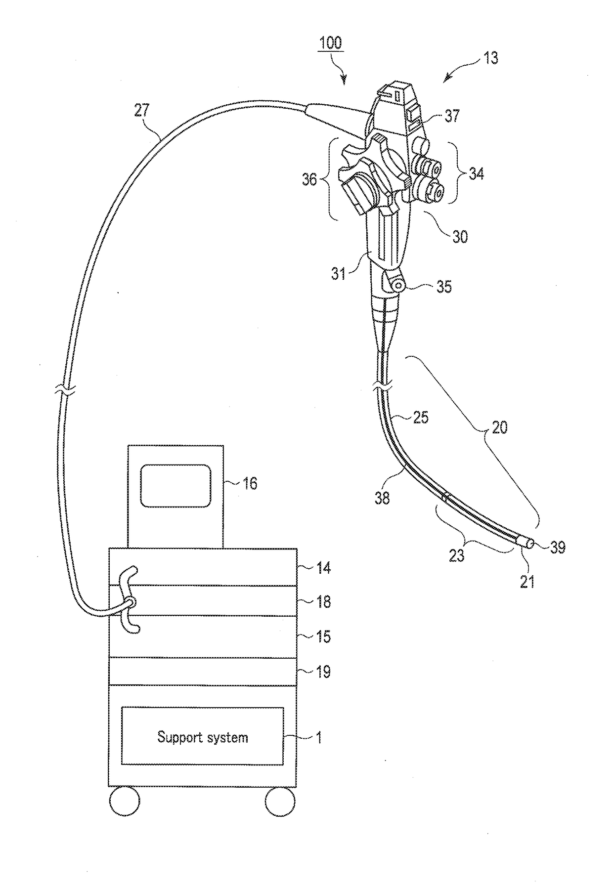
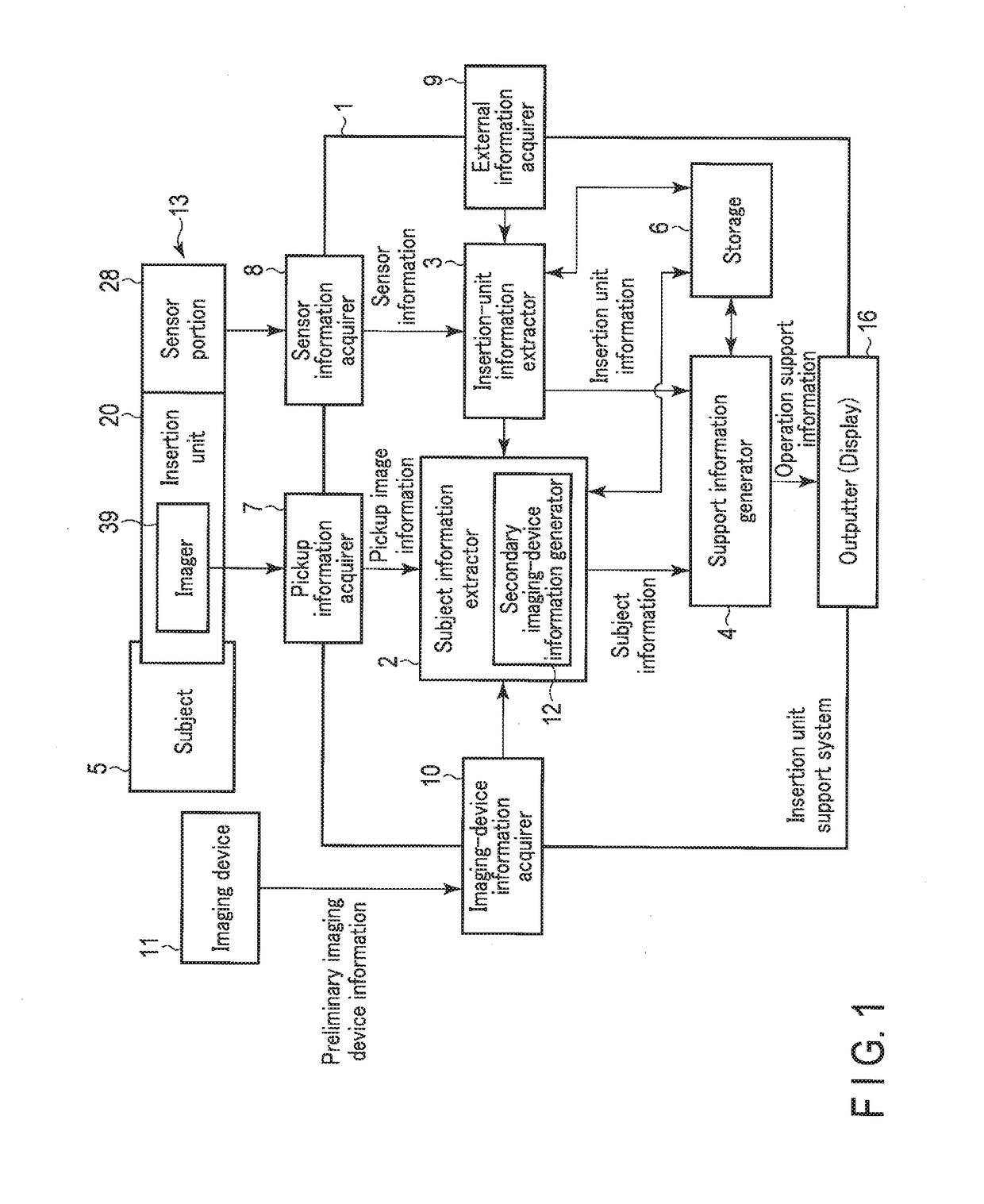
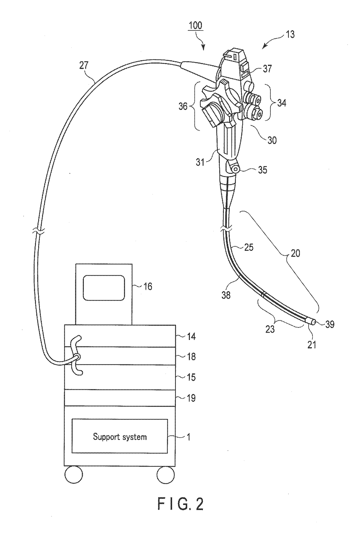
[0040]FIG. 1 shows a configuration example of an insertion unit support system provided for a tubular insertion system according to one embodiment of the present invention. FIG. 2 shows external structures of an endoscope having the insertion unit support system, and FIG. 3 shows bending directions of a bending portion at the distal end of an insertion portion of the endoscope. The tubular insertion system according to this embodiment will be described in detail, taking a flexible endoscope for medical use (scope for an upper gastrointestinal tract or a large bowel, scope using ultrasonic waves, cystoscope, pyeloscope, and so on) as an example. As a matter of course, the embodiment is not limited to flexible endoscopes for medical use. The embodiment is broadly applicable to any other tubular insertion systems having a shape bendable in at least a longitudinal portion, such as endoscopes for industrial use, rigid scopes having a partial bending mechanism, manipulators (robot arms), ...


PUM


Abstract

The insertion unit support system is provided for a tubular insertion system, and generates lumen information including the shape and location of a lumen based on the pre-acquired information about the lumen of a subject as an observation target that includes image information of two- or higher dimensional images, i.e., three-dimensional images or three-dimensional tomograms, so that the lumen information is used as support information for inserting the insertion unit of an endoscope. The lumens of the subjects targeted for the support of the insertion unit support system may vary in shape and location, and are deformed according to the shape of an inserted insertion unit. Thus, the support information is corrected and updated based on the deformation.

Description

CROSS-REFERENCE TO RELATED APPLICATIONS[0001]This is a Continuation Application of PCT Application No. PCT / JP2015 / 079575, filed Oct. 20, 2015, which was published under PCT Article 21(2) in Japanese.BACKGROUND OF THE INVENTION1. Field of the Invention[0002]The present invention relates to an insertion unit support system for supporting operations of a tubular insertion system as typified by a flexible endoscope, a catheter, or the like that is adapted to be inserted into lumens for performing observation and treatment procedures such as repair, remedy, and sampling.2. Description of the Related Art[0003]An endoscope is generally known as one example of a tubular insertion system that performs observation, etc., while being inserted into any lumen or body cavity. An insertion portion (or insertion unit) of an endoscope, once inserted into a lumen, does not allow for direct visual recognition of its position or bending form. As such, skill and experience are required to determine the ...

Claims


Application Information

Patent Timeline
IPC IPC(8): A61B34/20A61B1/05A61B1/00A61B6/02A61B6/03A61B5/055A61B8/08
CPCA61B34/20A61B1/05A61B1/00059A61B6/022A61B6/032A61B5/055A61B1/0005A61B8/0841A61B6/027A61B2034/2061A61B2034/2065A61B1/00009A61B34/25A61B5/0055A61B6/463A61B8/12A61B8/463A61B5/066A61B2034/107
Inventor HANE, JUNFUJITA, HIROMASA
Owner OLYMPUS CORP
Why Eureka
Try Eureka