Power detector

a detector and power technology, applied in the field of power detectors, can solve the problems of difficult to have a wide input dynamic range at a low supply voltage, difficult to ignore temperature variations, and difficult to infer amplifier performance, so as to minimize errors, wide input dynamic range, and minimize errors

Active Publication Date: 2018-08-23
DIALOG SEMICON KOREA INC
View PDF4 Cites 1 Cited by
  • Summary
  • Abstract
  • Description
  • Claims
  • Application Information

AI Technical Summary

Benefits of technology

[0010]As described below, according to embodiments of the present invention, a power detector (PD) can perform calibration to minimize errors caused by a process variation and a temperature variation in a structure in which allows a wide input dynamic range of the PD at a low supply voltage.
[0011]According to the embodiments of the present invention, since the PD has a structure that can be used even at a low voltage and a high frequency, a PD in whi

Problems solved by technology

However, the peak detector has a structure in which it is difficult to infer the performance of the amplifier when being used in a range from several hundred MHz to several GHz and is difficult to have a wide input dynamic range at a low supply voltage (VDD).
However, since the RMS detector or t

Method used


Image

  • Power detector
  • Power detector
  • Power detector

Examples


Embodiment Construction

[0019]Hereinafter, embodiments of the present invention will be described in detail with reference to the accompanying drawings.

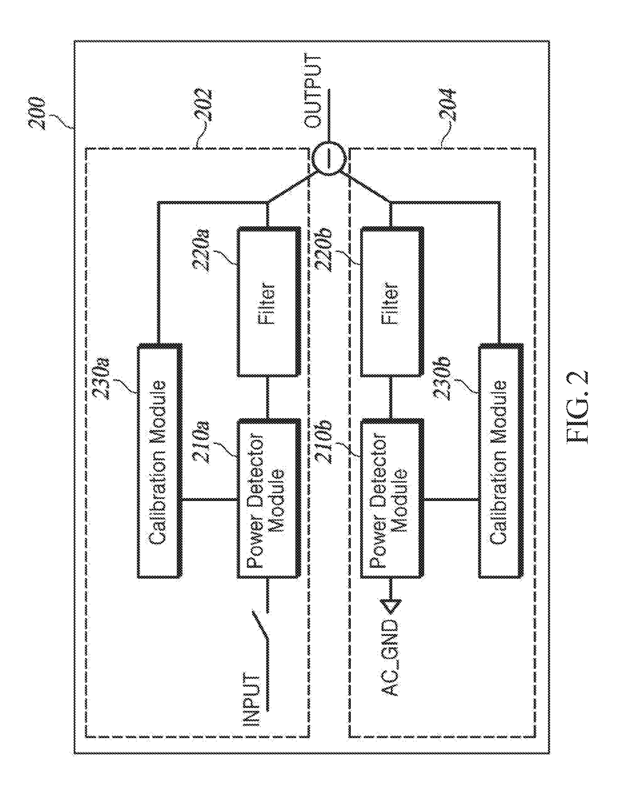
[0020]FIG. 2 is a block diagram schematically illustrating a power detector (PD) according to one embodiment of the present invention.

[0021]The PD 200 according to the present embodiment includes a power level determiner 202 and a signal determiner 204, in which PD modules 210a and 210b, filters 220a and 220b, and calibration modules 230a and 230b are each implemented as a pair. Components included in the PD 200 are not limited thereto.

[0022]The power level determiner 202 determines a power level of an input signal in real time. The power level determiner 202 includes a first PD module 210a, a first filter 220a, and a first calibration module 230a.

[0023]A terminal of the first PD module 210a is connected to an input terminal and the other terminal of the first PD module 210a is connected to the first filter 220a. A terminal of the first filter 220a is conn...


PUM


Abstract

Disclosed is a power detector. The power detector in which calibration is performed to minimize errors caused by a process variation and a temperature variation in a structure that allows a wide input dynamic range of the power detector at a low supply voltage is provided.

Description

BACKGROUND OF THE INVENTIONField of Invention[0001]The present invention relates to a power detector in which calibration is performed to minimize errors caused by a process variation and a temperature variation in a low supply voltage (VDD).Description of Prior Art[0002]Contents described below provide only background information related to embodiments of the present invention and do not describe the related art.[0003]A conventional power detector (PD) illustrated in FIG. 1 serves to convert a voltage into a current domain in a first N-type amplifier (MN1) and a second N-type amplifier (MN2). The conventional PD may serve as a rectifier after combining two output currents of a first N-type amplifier (MN1) and a second N-type amplifier (MN2) in a first P-type amplifier (MP1). The conventional PD serves to apply an output thereof to a second P-type amplifier (MP2) and convert the output into a voltage domain using a first resistor (R1). Since an undesired high-frequency component sti...

Claims


Application Information

Patent Timeline
IPC IPC(8): G01R21/133G01R35/00
CPCG01R35/005G01R21/133
Inventor KO, DONGHYUN
Owner DIALOG SEMICON KOREA INC
Why Eureka
Try Eureka