Optical device, display apparatus and driving method thereof

a technology of optical devices and display devices, applied in the field of display technology, can solve the problems of difficult to switch the original state of the viewing viewing of consumer electronics and privacy leakage becoming an inevitable problem

Active Publication Date: 2018-08-23
BOE TECH GRP CO LTD
View PDF6 Cites 8 Cited by
  • Summary
  • Abstract
  • Description
  • Claims
  • Application Information

AI Technical Summary

Benefits of technology

[0013]Under the irradiation of the light source, the optically deformable film may be configured to deform to form a lens structure through which the light incident on the first surface passes and exits from the second surface. An illumination area by the light passing through the first surface and exiting from the second surface may be increased or decreased.

Problems solved by technology

As consumer electronics are frequently used in public places, privacy leaks are becoming an inevitable problem.
However, with these methods, when a user needs to increase the viewing field, it is difficult to switch the consumer electronics to the original state of the viewing.

Method used


Image

  • Optical device, display apparatus and driving method thereof
  • Optical device, display apparatus and driving method thereof
  • Optical device, display apparatus and driving method thereof

Examples


embodiment i

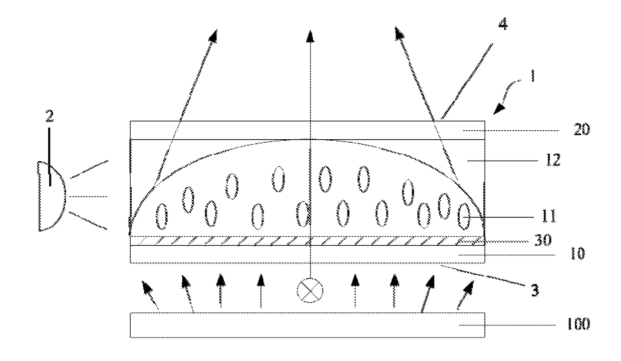
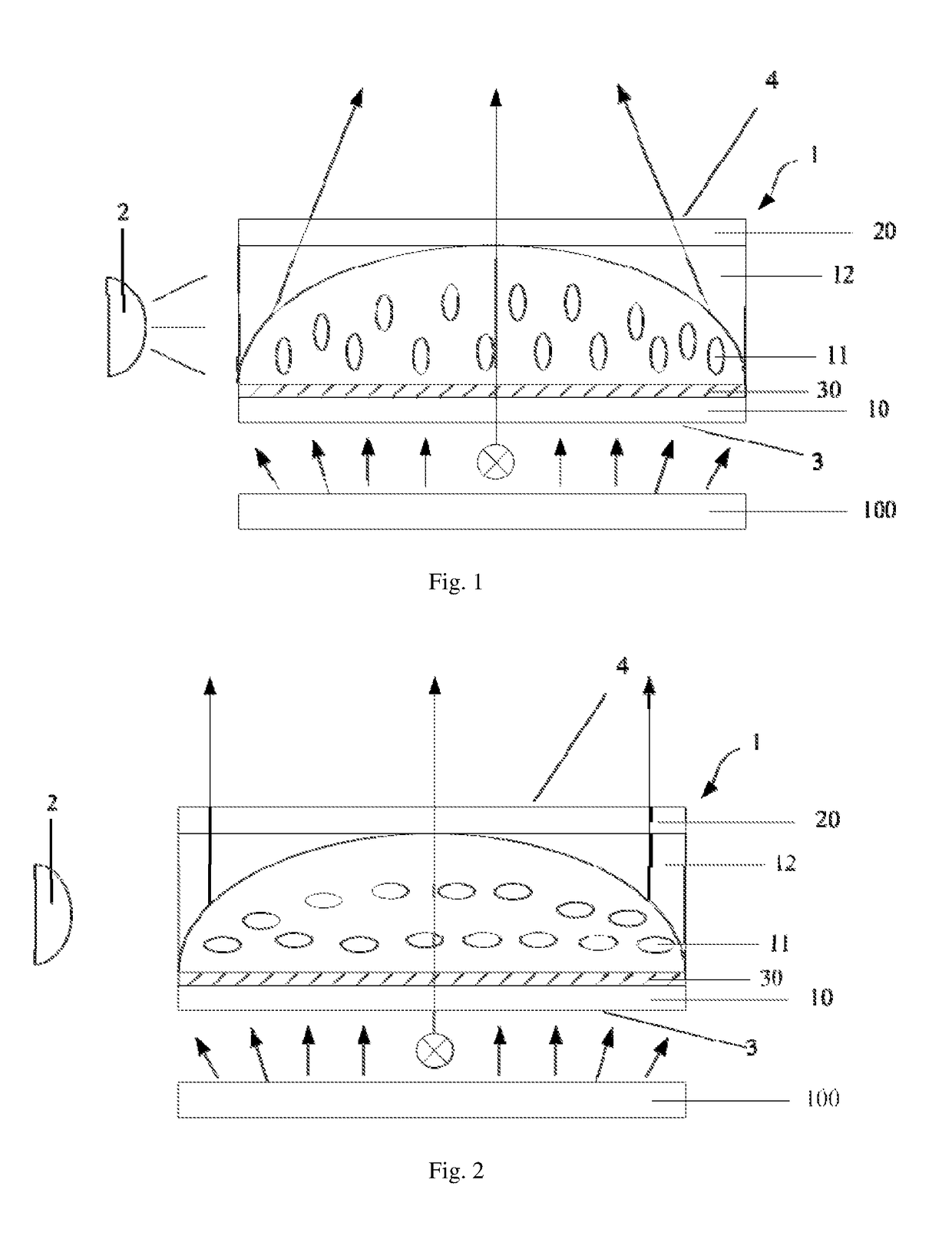
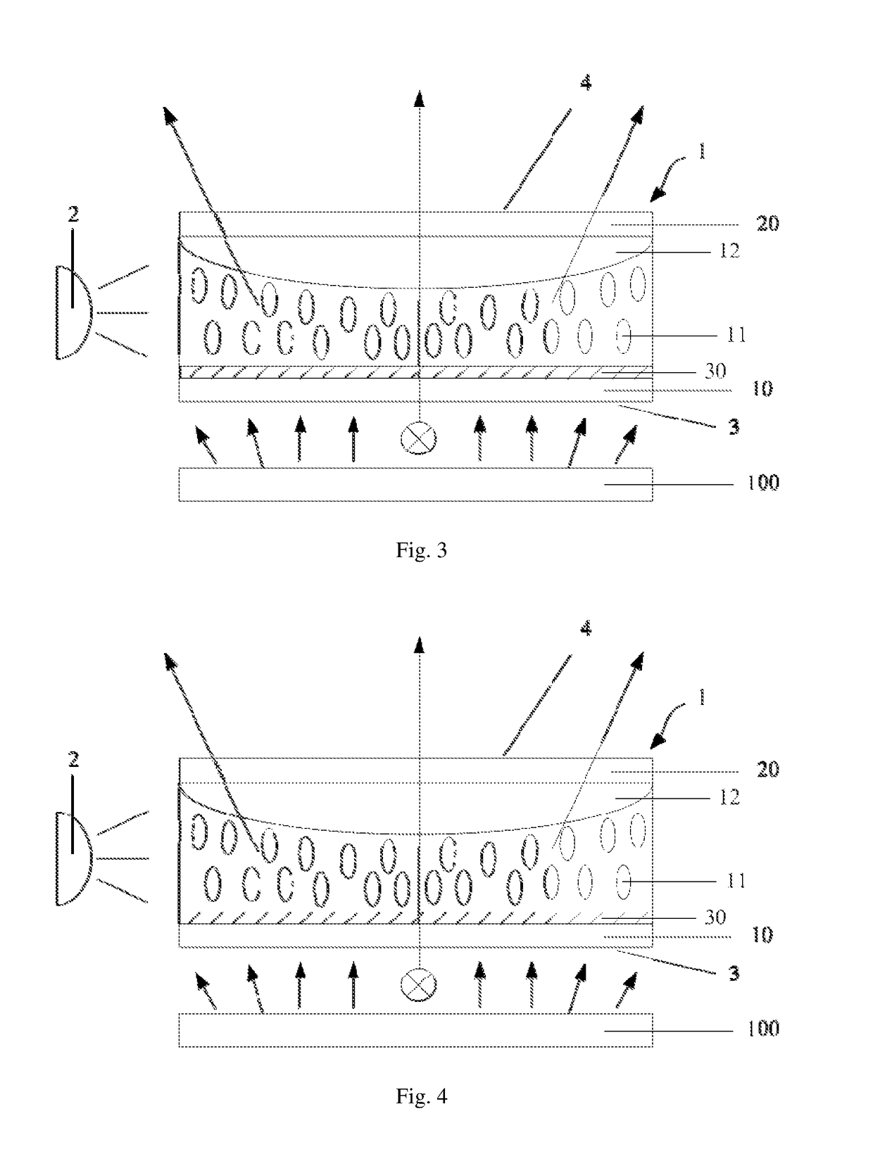
[0034]As shown in FIGS. 1 to 4, an optical device in accordance with one embodiment of the present invention comprises a light-controllable optical element 1 and a light source 2. The optical element 1 comprises a first surface 3 and a second surface 4 opposite the first surface 3, and side surfaces adjacent to the first and second surfaces. A light incident on the first surface 3 is emitted from the second surface 4. The light source 2 is provided at a side of the optical element 1. When the light source 2 is turned off, the optical element 1 does not adjust the light incident on the first surface 3, as shown in FIGS. 2 and 4. When the light source 2 is turned on, the optical element 1 adjusts the light incident on the first surface 3 and exiting from the second surface 4 to increase the illumination area (as shown in FIG. 3) or reduce the illumination area (as shown in FIG. 1) under the irradiation of the light source 2. Herein the illumination area refers to an illumination area ...

embodiment ii

[0055]In another embodiment of the present invention, the light may be adjusted by photo-deformation of an optical film, thereby increasing or decreasing the illumination area to switch the size of the viewing angle.

[0056]As shown in FIGS. 5 to 8, the optical element 1 is an optically deformable film comprising a first surface 3 and a second surface 4 opposite the first surface 3, and side surfaces adjacent to the first and second surfaces. The light source 2 is disposed near the side surface. The optically deformable film 1 is made of a photo-deformable material. When the light source 2 is turned off, the optically deformable film 1 is not deformed, and the light incident from the first surface is not be adjusted as shown in FIG. 5. When the light source 2 is turned on, the photo-deformable material may deform, and the optically deformable film 1 may be deformed to form a lens structure. Accordingly, the illumination area of the light incident from the first surface passing through...

embodiment iii

[0068]As shown in FIG. 9, there is provided a display device including a display panel 100 and an optical device provided on a display side of the display panel 100. The optical device may be the optical device in accordance with Embodiment 1 or Embodiment 2 of the present invention. Such optically controllable optical device may quickly switch the size of the display viewing angle, thereby helping to achieve anti-peeping and improving the user experience.

[0069]In one embodiment, the controllable optical element of the optical device comprises an alignment layer made of a polymer having a photoisomer group. When the light source of the optical device is turned off, the alignment layer aligns the liquid crystal molecules in a first direction, the first direction being perpendicular to the polarization direction of a linearly polarized light exiting from the display panel, the polarization direction being in a horizontal plane with the first direction, and the horizontal plane being p...


PUM

PropertyMeasurementUnit
molecular lengthaaaaaaaaaa
refractive indexaaaaaaaaaa

Abstract

An optical device for a display panel. The optical device comprises an optical element (1). The optical element (1) may include a first surface (3) and a second surface (4) opposite the first surface, and side surfaces. The optical device may further comprise a light source (2) facing one of the side surfaces of the optical element (1). The optical element (1) may comprise a compound containing a photoisomer group. The photoisomer group may undergo a photoisomerization under an irradiation of the light source. Accordingly, an illumination area by a light passing through the first surface (3) and exiting from the second surface (4) may increase or decrease.

Description

CROSS-REFERENCE TO RELATED APPLICATIONS[0001]This application claims the benefit of the filing date of Chinese Patent Application No. 201610596049.7 filed on Jul. 26, 2016 the disclosure of which is hereby incorporated by reference.TECHNICAL FIELD[0002]This invention relates to display technology, more particularly to an optical device, display apparatus and driving method thereof.BACKGROUND[0003]As consumer electronics are frequently used in public places, privacy leaks are becoming an inevitable problem. To meet the needs of privacy protection, some anti-peeping technologies have been developed, such as anti-peeping polymeric membranes. However, with these methods, when a user needs to increase the viewing field, it is difficult to switch the consumer electronics to the original state of the viewing.BRIEF SUMMARY[0004]Accordingly, one example of the present invention is an optical device comprising an optical element. The optical element may include a first surface and a second su...

Claims


Application Information

Patent Timeline
Patent Type & Authority Applications(United States)
IPC IPC(8): G02F1/29G02F1/1337G02F1/1335
CPCG02F1/293G02F1/133711G02F1/133788G02F1/133526G02F1/1335G02F1/1337G02F1/0126G02F1/1323G02B26/02G02F1/133738G02F1/133742G02F1/133769
Inventor JI, CHUNYANLI, WENBO
Owner BOE TECH GRP CO LTD
Why Eureka
Try Eureka