Method for manufacturing liquid crystal display device

a liquid crystal display and manufacturing method technology, applied in the manufacture of electrode systems, electric discharge tubes/lamps, instruments, etc., can solve the problems of foreign matter defects, rubbing, and breaking of thin film transistor elements, and achieve the effect of improving display quality

Active Publication Date: 2016-06-23
SHARP KK
View PDF0 Cites 3 Cited by
  • Summary
  • Abstract
  • Description
  • Claims
  • Application Information

AI Technical Summary

Benefits of technology

[0034]One aspect of the present invention can provide a method for manufacturing a liquid crystal display device including a photo-alignment film and capable of sufficiently improving the display quality.

Problems solved by technology

However, the rubbing causes problems such as foreign-matter defects due to dust of cloth and display unevenness, and breaking of thin film transistor elements due to static electricity generated in rubbing with a cloth.
Further, as the definition of the display devices such as tablet PCs and smartphones more and more increases, it becomes more and more difficult to uniformly align the liquid crystal molecules by rubbing, in which the alignment precision is restricted by the density of the pile of a cloth.

Method used


Image

  • Method for manufacturing liquid crystal display device
  • Method for manufacturing liquid crystal display device
  • Method for manufacturing liquid crystal display device

Examples


example 1

[0044]In Example 1, a photo-alignment-film material containing two polymers was used. The following describes a method for manufacturing a liquid crystal display device according to Example 1.

(Structure of Liquid Crystal Display Device)

[0045]A liquid crystal display device has an FFS-mode electrode structure, and the pre-tilt angle is 0°.

(Photo-Alignment-Film Material)

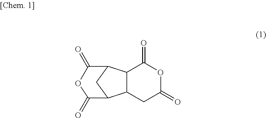
[0046]A mixture of two polymers at a weight ratio of 50:50 was used as a solid matter. One of the two polymers is a polymer including a methacrylic backbone and a photo-reactive cinnamate group in a side chain, and the other is a polyamic acid which is obtained by reacting 1,2,3,4-cyclobutanetetracarboxylic dianhydride (CBDA) and a diamine including a biphenyl structure and which is free from a photo-functional group and a side chain. A solvent used was a mixture of N-methyl-pyrrolidone and butyl cellosolve at a weight ratio of 50:50. The solid concentration was 4% by weight. The cinnamate group is a photodimerizable a...

examples 2-1 to 2-6

[0071]For the liquid crystal display devices manufactured by the methods for manufacturing a liquid crystal display device of Examples 2-1 to 2-6, the pre-heating temperatures and the results of evaluating the display quality are shown in Table 1.

(Evaluation Method of Display Quality)

[0072]The display quality was evaluated on a four-level scale. Level 1: the contrast was not lower than 1200. Level 2: the contrast was not lower than 1000 but lower than 1200. Level 3: the contrast was not lower than 500 but lower than 1000. Level 4: the contrast was lower than 500 or an alignment defect was visually observed. Those of Levels 1 to 3 were evaluated as suitable for products, whereas those of Level 4 were evaluated as not suitable for products.

(Measurement of Contrast)

[0073]The contrast was measured by the formula: (Contrast)=(luminance of white screen) / (luminance of black screen). When the display shows a white screen, a voltage for the maximum luminance is applied. When the display show...

example 2-1

[0075]The result of evaluating the display quality was Level 1 and was much better than those of Examples 2-3 to 2-6. This is presumably because the orientational order of the polymer by the self-assembly was sufficiently improved. Thus, the method for manufacturing a liquid crystal display device of Example 2-1 can sufficiently improve the display quality.


PUM

PropertyMeasurementUnit
pre-tilt angleaaaaaaaaaa
temperatureaaaaaaaaaa

Abstract

The present invention provides a method for manufacturing a liquid crystal display device including a photo-alignment film and capable of sufficiently improving the display quality. The method for manufacturing a liquid crystal display device of the present invention is a method for manufacturing a liquid crystal display device including a photo-alignment film. The method for manufacturing a liquid crystal display device successively includes a step (1) of forming on a substrate a film from a photo-alignment-film material that contains a solvent, a polymer including a photo-functional group that is capable of causing at least one chemical reaction selected from the group consisting of photodimerization, photoisomerization, and photo-Fries rearrangement, and a polymer including a polyamic acid backbone and free from the photo-functional group; a step (2) of pre-heating the film to evaporate the solvent; a step (3) of irradiating the pre-heated film with polarized light; and a step (4) of main-heating the polarized-light-irradiated film. The liquid crystal display device is of an in-plane switching mode or a fringe field switching mode in each of which a pre-tilt angle is substantially 0°.

Description

TECHNICAL FIELD[0001]The present invention relates to a method for manufacturing a liquid crystal display device. The present invention specifically relates to a method for manufacturing a liquid crystal display device in relation to the conditions for forming an alignment film.BACKGROUND ART[0002]Thin-profile display devices such as liquid crystal display devices have rapidly spread in recent years, and are widely used for not only televisions but also electronic books, digital photo frames, industrial appliance (IA), personal computers (PCs), tablet PCs, smartphones, and the like. These applications demand a wide variety of performance, and various liquid crystal display modes are developed.[0003]Frequently used liquid crystal display modes include an in-plane switching (IPS) mode and a fringe field switching (FFS) mode in which the liquid crystal molecules having positive or negative anisotropy of dielectric constant are aligned in the direction horizontal to the main surface of ...

Claims


Application Information

Patent Timeline
Patent Type & Authority Applications(United States)
IPC IPC(8): G02F1/1337
CPCG02F1/133711G02F1/133788C09D179/08
Inventor MIYAKE, ISAMUMIYACHI, KOICHIASAGI, HIROAKI
Owner SHARP KK
Why Eureka
Try Eureka