
Peelable cable jacket having designed microstructures and methods for making peelable cable jackets having designed microstructures

a technology of microstructure and peeling cable, which is applied in the direction of insulating conductor/cable, cable, insulated conductor, etc., can solve the problems of cable coating tearing to access such internal components during connection or installation, and the advancement of jacket mechanical properties often comes at the expense of the jacket coating

Active Publication Date: 2018-08-23
DOW GLOBAL TECH LLC
View PDF17 Cites 3 Cited by
  • Summary
  • Abstract
  • Description
  • Claims
  • Application Information

AI Technical Summary

Benefits of technology

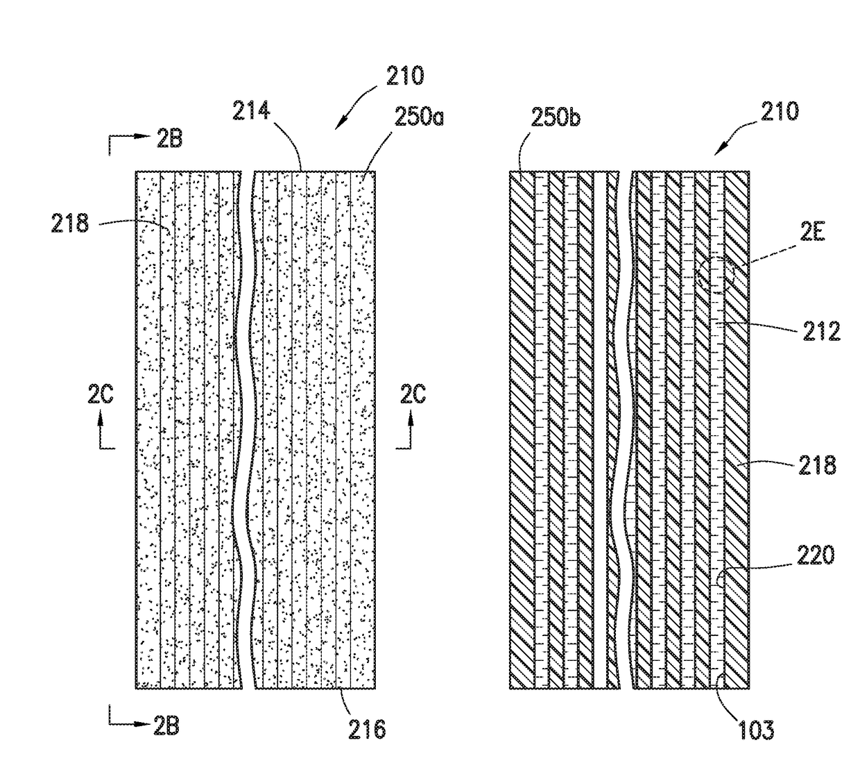
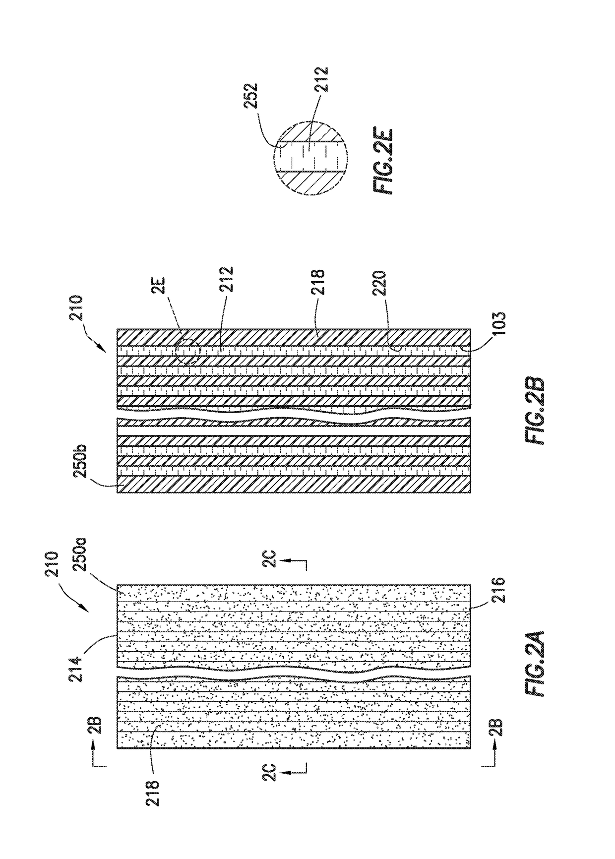
The patent is about a type of coated conductor that has a layer of peelable plastic around it. This layer has tiny spaces that are filled with air. The technical benefit of this design is that it helps to create a pocket of air around the conductor, which helps to prevent damage to the conductor during bending or other forms of manipulation. This makes the coated conductor more durable and reliable.

Problems solved by technology

As a result, tearing the cable coating to access such internal components during connection or installation is difficult.
While some attempts have been made to provide cable jackets with easy access to internal components, such advancements often come at the expense of the jackets' mechanical properties.

Method used


Image

  • Peelable cable jacket having designed microstructures and methods for making peelable cable jackets having designed microstructures
  • Peelable cable jacket having designed microstructures and methods for making peelable cable jackets having designed microstructures
  • Peelable cable jacket having designed microstructures and methods for making peelable cable jackets having designed microstructures

Examples


examples

Sample Preparation

Air-Filled Microcapillary Samples

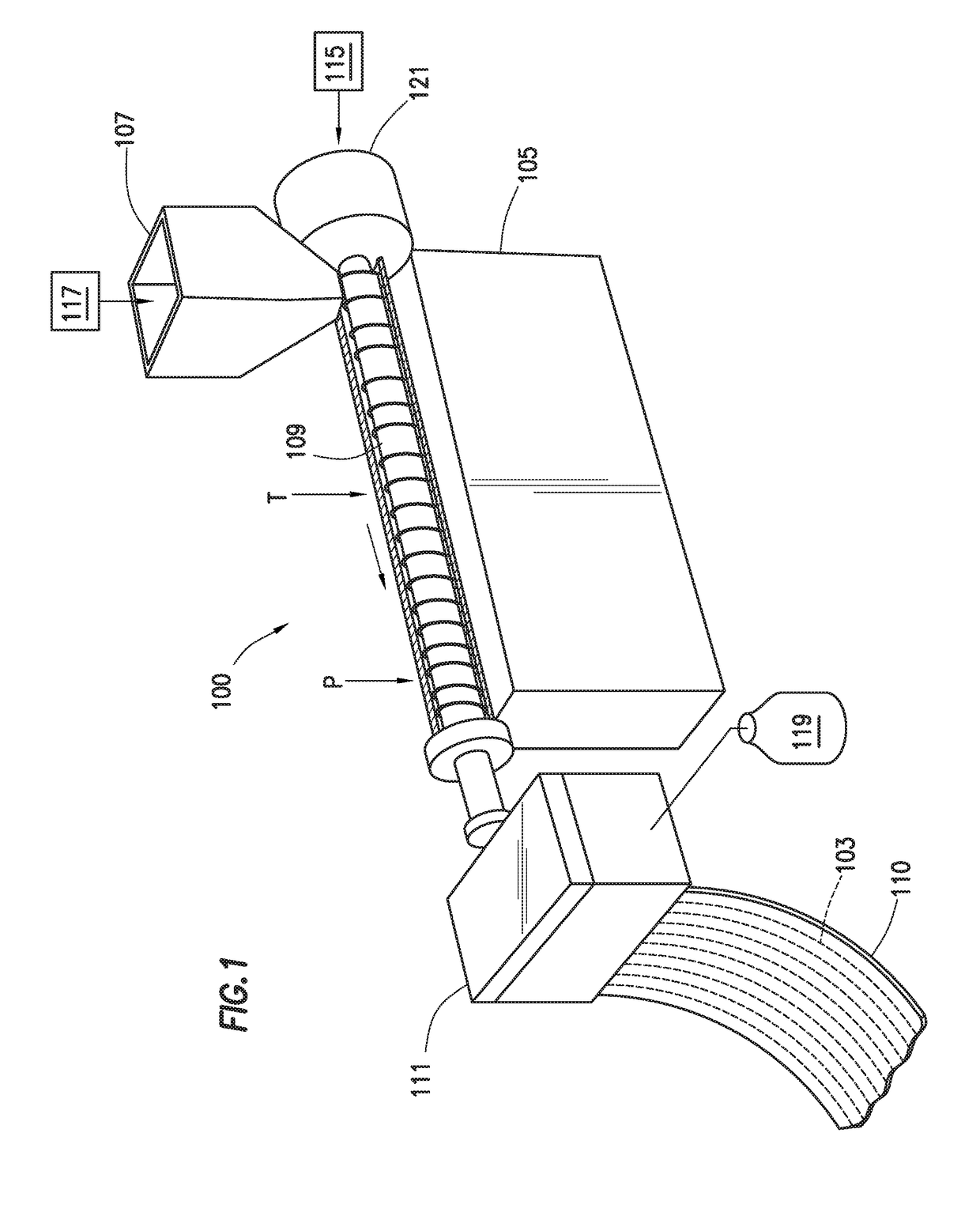
[0145]Prepare four samples (S1-S4) using a tape-extrusion system consisting of a single-screw extruder (3.81-cm Killion extruder) fitted with a microcapillary die capable of handling a polymer melt and an air stream, as schematically depicted in FIG. 1. The die to be used in these Examples is described in detail in PCT Published Patent Application No. WO 2014 / 003761, specifically with respect to FIGS. 4A and 4A1, and the corresponding text of the written description, which is incorporated herein by reference. The die has 42 microcapillary nozzles, a width of 5 cm, and a die gap of 1.5 mm. Each microcapillary nozzle has an outer diameter of 0.38 mm and an inner diameter of 0.19 mm. The plant air is supplied by an air line with a flow meter, which is fully open prior to heating the machine to prevent blockage of the microcapillary nozzles by the backflow of polymer melt. In preparing the microcapillary sheets, first the extruder, gear...

example

[0149]Analyze each of CS1, CS2, and S1-S5 according to the Test Methods provided above. The results are provided in Table 6, below.

TABLE 6Properties of CS1, CS2, and S1-S5Tear% TearTensileTensileStrengthReductionStrengthElongationSample(lb / in.)vs. Control(psi)(%)MDPE-based SamplesCS1839.3—4,666910S1197.376.53,168807S2167.380.12,530693S5413.450.73,388857LDPE-based SamplesCS2295.7—2,836661S3128.156.72,203523S483.171.92,040598

[0150]CS1 is a sample representing a solid tape made of commercial MDPE, which shows a tear strength of about 840 lb / in. and the typical tensile and elongation properties for this compound. S1 and S2 show the same compound extruded into a tape with air-filled microcapillaries. When torn in the axial direction along one of the capillaries, the tear strength is shown to be reduced by 76 and 80% respectively depending on the size of the microcapillaries. S5 shows that a sample having microcapillaries filled with a polyolefin elastomer (ENGAGE™ 8200) can also provide ...


PUM

PropertyMeasurementUnit
Lengthaaaaaaaaaa
Lengthaaaaaaaaaa
Lengthaaaaaaaaaa

Abstract

Coated conductors comprising a conductor and a peelable polymeric coating at least partially surrounding the conductor, where the peelable polymeric coating comprises from 1 to 8 microcapillaries that define individual, discrete void spaces. Also disclosed are methods for making such coated conductors.

Description

REFERENCE TO RELATED APPLICATIONS[0001]The present application claims the benefit of U.S. Provisional Application No. 62 / 233,620, filed on Sep. 28, 2015.FIELD[0002]Various embodiments of the present invention relate to cable coatings and jackets having microcapillary structures which allow for ease of peeling.INTRODUCTION[0003]Cables often require access to their core for ease of connection and installation. Generally, cables are designed for maximum protection of the internal components, requiring the use of tough materials. As a result, tearing the cable coating to access such internal components during connection or installation is difficult. For instance, when connecting cables, a skilled installer must typically use sharp cutting tools to split open the jacket and then use special tools to access the cable's internal components. The costs of network installation and subsequent maintenance or cable replacement can be lowered by usage of cables in which the inner components are e...

Claims


Application Information

Patent Timeline
IPC IPC(8): H01B7/28H01B13/14H01B7/24
CPCH01B7/28H01B13/14H01B7/24H01B7/185C08L23/06C09D123/06H01B3/441Y02A30/14
Inventor ESSEGHIR, MOHAMEDHUANG, WENYIKMIEC, CHESTER J.
Owner DOW GLOBAL TECH LLC
Learn More