Management server, management method and management system

a management server and management system technology, applied in the integration of power network operation systems, instruments, data processing applications, etc., can solve the problems of inefficient control of forward power flow or reverse power flow with respect to the entire group of facilities

Inactive Publication Date: 2018-08-23
KYOCERA CORP
View PDF113 Cites 4 Cited by
  • Summary
  • Abstract
  • Description
  • Claims
  • Application Information

AI Technical Summary

Problems solved by technology

Second, in a case where the forward power flow amount or the reverse power flow amount is suppressed by transmission of the power instruction message, there is possibility that the suppression control for the forward power flow or the reverse power flow is inefficiently performed with respect to the entire group of facilities managed by the management server when the power instruction message is uniformly transmitted to all facilities managed by the management server.

Method used


Image

  • Management server, management method and management system
  • Management server, management method and management system
  • Management server, management method and management system

Examples


first embodiment

[0027](Power Management System)

[0028]Hereinafter, a power management system according to a first embodiment will be described.

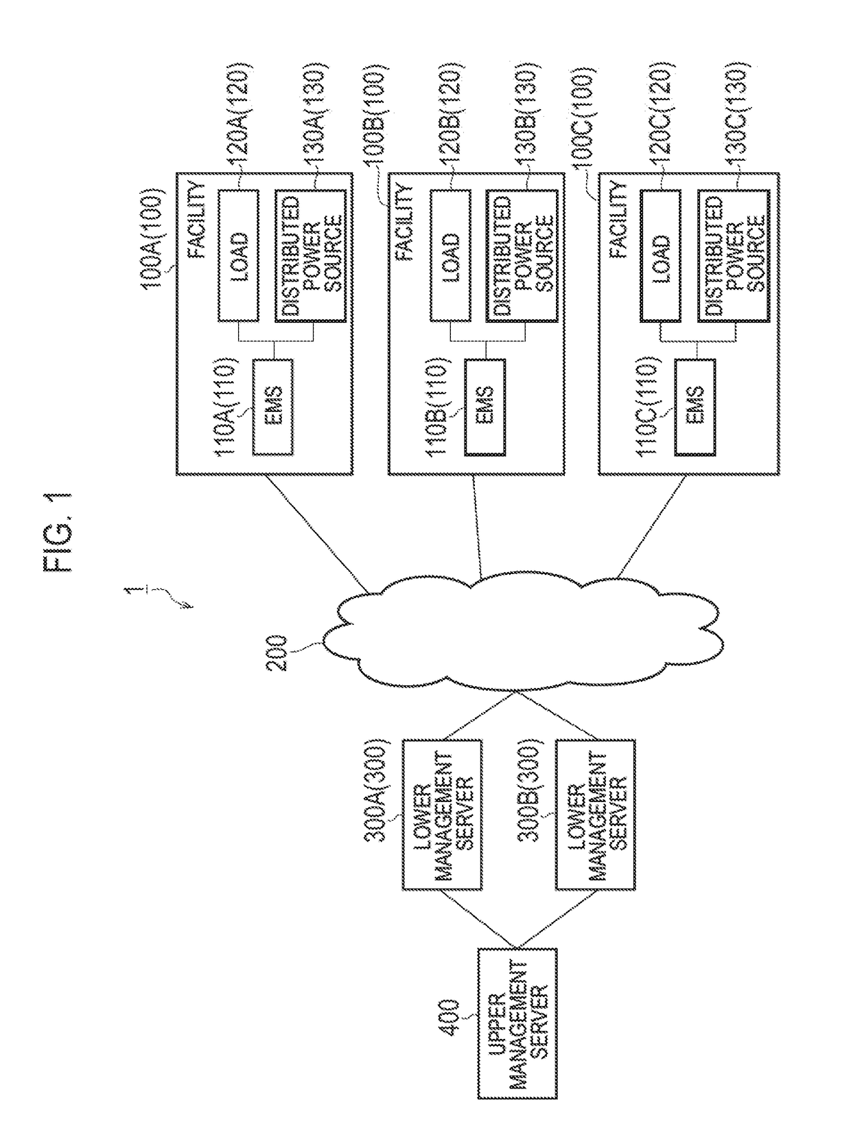
[0029]As illustrated in FIG. 1, a power management system 1 includes a facility 100, a network 200, a lower management server 300, and an upper management server 400.

[0030]The facility 100 includes an EMS 110, a load 120, and a distributed power source 130. The EMS 110 is an apparatus configured to manage power of an equipment installed in the facility 100 (Energy Management System). The load 120 is an equipment configured to consume power. The load 120 includes equipments, for example, refrigerators, lightings, air conditioners, televisions, and the like. The load 120 may include one equipment or may include a plurality of equipments. The distributed power source 130 is an equipment configured to generate power or store power. The distributed power source 130 includes equipments, for example, a solar cell, a fuel cell, a storage battery, and the like. The di...

specific example

[0067]A specific example of the supply and demand adjustment plan according to the first embodiment will be described below. Here, a specific example of suppression plan of the forward power flow amount is illustrated.

[0068]In FIG. 5, a case where a facility 100A to a facility 100D are managed by a lower management server 300 is illustrated as an example. The storage battery and a power generation apparatus are installed in one or more facility 100 of the facilities 100A to 100D. DR is a power instruction message (Demand Response) transmitted to the lower management server 300 from the upper management server 400. Also, the vertical axis in FIG. 5 is represented by an index with the start point of suppression of the forward power flow amount as zero.

[0069]In this case, the lower management server 300 determines the supply and demand adjustment plan in order to suppress a forward power flow amount according to DR received from the upper management server 400. The supply and demand ad...

second embodiment

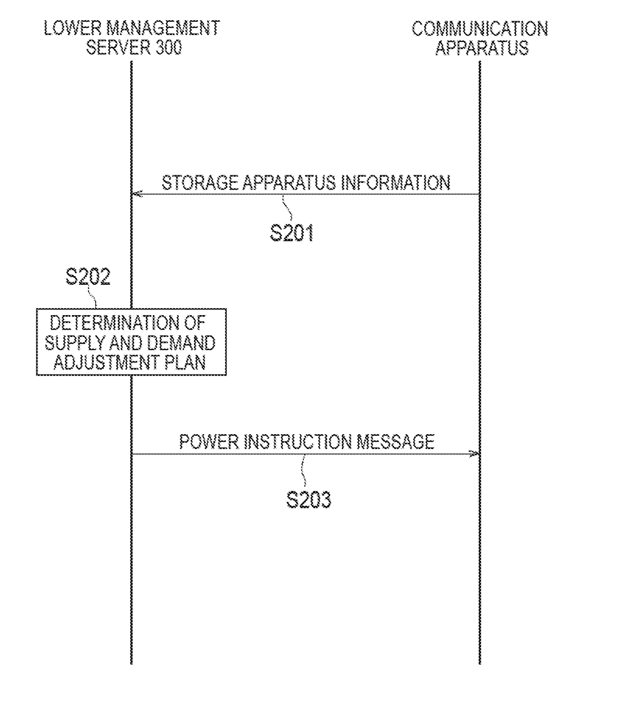
[0098](Power Management System)

[0099]Hereinafter, a power management system according to a second embodiment will be described. As illustrated in FIG. 6, a power management system 1 includes a facility 100, a network 200, a lower management server 300, and an upper management server 400. The power management system 1 according to the second embodiment has the same configuration as the one according to the first embodiment except that the facility 100 has a communication apparatus 150 instead of the EMS 110. The facility 100 may include both of the EMS 110 and the communication apparatus 150.

[0100]In the second embodiment, a consumer's facility communication apparatus 1 is an apparatus configured to manage power of an equipment installed in the facility 100 (Energy Management System) or a PCS (Power conditioning system) configured to control the distributed power source 130. The distributed power source 130 is an equipment configured to generate power. The distributed power source 13...


PUM


Abstract

A management server comprises a transmitter configured to transmit a power instruction message to a facility; and a manager configured to manage at least one of suppression influence information and storage apparatus information, the suppression influence information affecting a suppression of a forward power flow amount from a power grid to the facility or a reverse power flow amount from the facility to the power grid, the storage apparatus information being related to an energy storage apparatus installed in the facility. The transmitter is further configured to transmit the power instruction message to the facility, based on at least one of the suppression influence information and the storage apparatus information.

Description

TECHNICAL FIELD[0001]The present disclosure relates to a management server, a management method and a management system.BACKGROUND ART[0002]There has been known a power instruction message including a forward power flow suppression message for requesting control for a forward power flow amount (power supply amount) from a power grid to a facility (for example, DR; Demand Response) or a reverse power flow suppression message for requesting control for a reverse power flow amount from the facility to the power grid. The power instruction message is transmitted to a facility from a management server belonging to an electric power company, a power distribution company, or the like, through a communication line (for example, Patent Literature 1).[0003]Furthermore, there has been proposed a technology of decreasing power consumption in home appliances installed in the facility in response to reception of a forward power flow suppression message. Specifically, the forward power flow suppre...

Claims


Application Information

Patent Timeline
Patent Type & Authority Applications(United States)
IPC IPC(8): H02J3/14H02J3/38H02J3/46
CPCH02J3/14H02J3/382H02J3/46H02J13/00Y02B70/3225Y04S20/222G06Q50/06H02J3/32H02J3/381H02J2310/12H02J13/00004H02J13/00028H02J3/466Y04S20/242Y02B70/30
Inventor TERAI, RYOTAAIKAWA, SHINJIOKINO, KENTA
Owner KYOCERA CORP
Why Eureka
Try Eureka