Power feeding system, power receiving device, and power feeding method

Active Publication Date: 2018-08-23
ABLIC INC
View PDF3 Cites 2 Cited by
  • Summary
  • Abstract
  • Description
  • Claims
  • Application Information

AI Technical Summary

Benefits of technology

The present invention provides a power feeding system, a power receiving device, and a power feeding method that can reduce the risk of mistakenly determining if power should be supplied to the power receiving device.

Problems solved by technology

As a result, the periodic waveform variation in the excited voltage excited in the feeding coil is not detected, and the power feeding device determines that power supply to the power receiving device is not permitted.
However, in the above-mentioned power feeding system, for example, when a coupling coefficient between the feeding coil and the receiving coil is low, the electric power supplied from the power feeding device to the power receiving device decreases.
In this case, the periodic waveform variation in the excited voltage excited in the feeding coil is detected, and the power feeding device may thus erroneously determine that power supply to the power receiving device is required although the power supply is not required.

Method used


Image

  • Power feeding system, power receiving device, and power feeding method
  • Power feeding system, power receiving device, and power feeding method
  • Power feeding system, power receiving device, and power feeding method

Examples


Embodiment Construction

[0023]Now, a power feeding system according to one embodiment of the present invention is described with reference to the drawings.

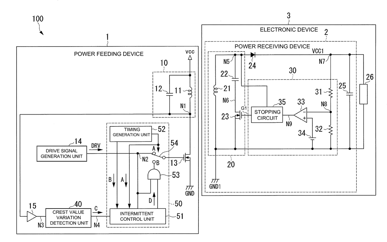
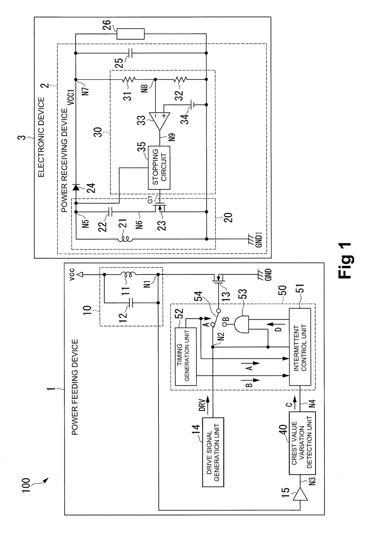
[0024]FIG. 1 is a block diagram for illustrating an example of a power feeding system 100 according to the embodiment of the present invention.

[0025]As illustrated in FIG. 1, the power feeding system 100 has a power feeding device 1 and an electronic device 3 having a power receiving device 2.

[0026]The power feeding system 100 is a system configured to supply electric power from the power feeding device 1 to the power receiving device 2 wirelessly (in a non-contact manner). For example, the power feeding system 100 is configured to supply electric power for operating a load 26 included in the power receiving device 2 from the power feeding device 1 to the power receiving device 2.

[0027]The electronic device 3 is, for example, a mobile phone terminal or a personal digital assistant (PDA), and has the power receiving device 2 and the load 26. Further, the ...


PUM


Abstract

A power feeding system includes a power feeding device and a power receiving device. The power receiving device includes: a resonant circuit having: a receiving coil; a resonant capacitor; and a resonance control transistor; and a resonance control unit configured to control the resonance control transistor based on received power by the receiving coil and power consumption of the load, and to control the resonance control transistor to keep the resonant circuit in a non-resonant state when the power consumption of the load becomes equal to or less than a predetermined value. The power feeding device includes a drive control unit configured to determine whether or not power supply to the power receiving device is required based on a periodic waveform variation in an excited voltage excited in the feeding coil.

Description

RELATED APPLICATIONS[0001]This application claims priority under 35 U.S.C. § 119 to Japanese Patent Application No. 2017-031437 filed on Feb. 22, 2017, the entire content of which is hereby incorporated by reference.BACKGROUND OF THE INVENTION1. Field of the Invention[0002]The present invention relates to a power feeding system, a power receiving device, and a power feeding method.2. Description of the Related Art[0003]In recent years, there has been known a power feeding system configured to supply electric power wirelessly through electromagnetic induction or electromagnetic coupling between a feeding coil and a receiving coil (see, for example, Japanese Patent Application Laid-open No. 2015-70689).[0004]In the power feeding system described in Japanese Patent Application Laid-open No. 2015-70689, a power receiving device has a resonant circuit having a receiving coil, a resonant capacitor, and a resonance control transistor configured to control a resonant state, and a power feed...

Claims


Application Information

Patent Timeline
IPC IPC(8): H02J50/12H02J50/60H02J7/02
CPCH02J50/12H02J50/60H02J7/025
Inventor HOSHINO, MASAFUMI
Owner ABLIC INC
Why Eureka
Try Eureka