Pain measurement device and pain measurement system

a measurement device and pain technology, applied in the field of pain measurement devices, can solve the problems of patients often suffering disadvantages by underestimating pain, and achieve the effect of improving measurement precision

Inactive Publication Date: 2018-08-30
OSAKA UNIV
View PDF3 Cites 3 Cited by
  • Summary
  • Abstract
  • Description
  • Claims
  • Application Information

AI Technical Summary

Benefits of technology

[0027]According to one aspect of the present invention, pain being experienced by a subj

Problems solved by technology

Patients often suffer disadvan

Method used


Image

  • Pain measurement device and pain measurement system
  • Pain measurement device and pain measurement system
  • Pain measurement device and pain measurement system

Examples


embodiment 1

[Configuration of Pain Measurement System]

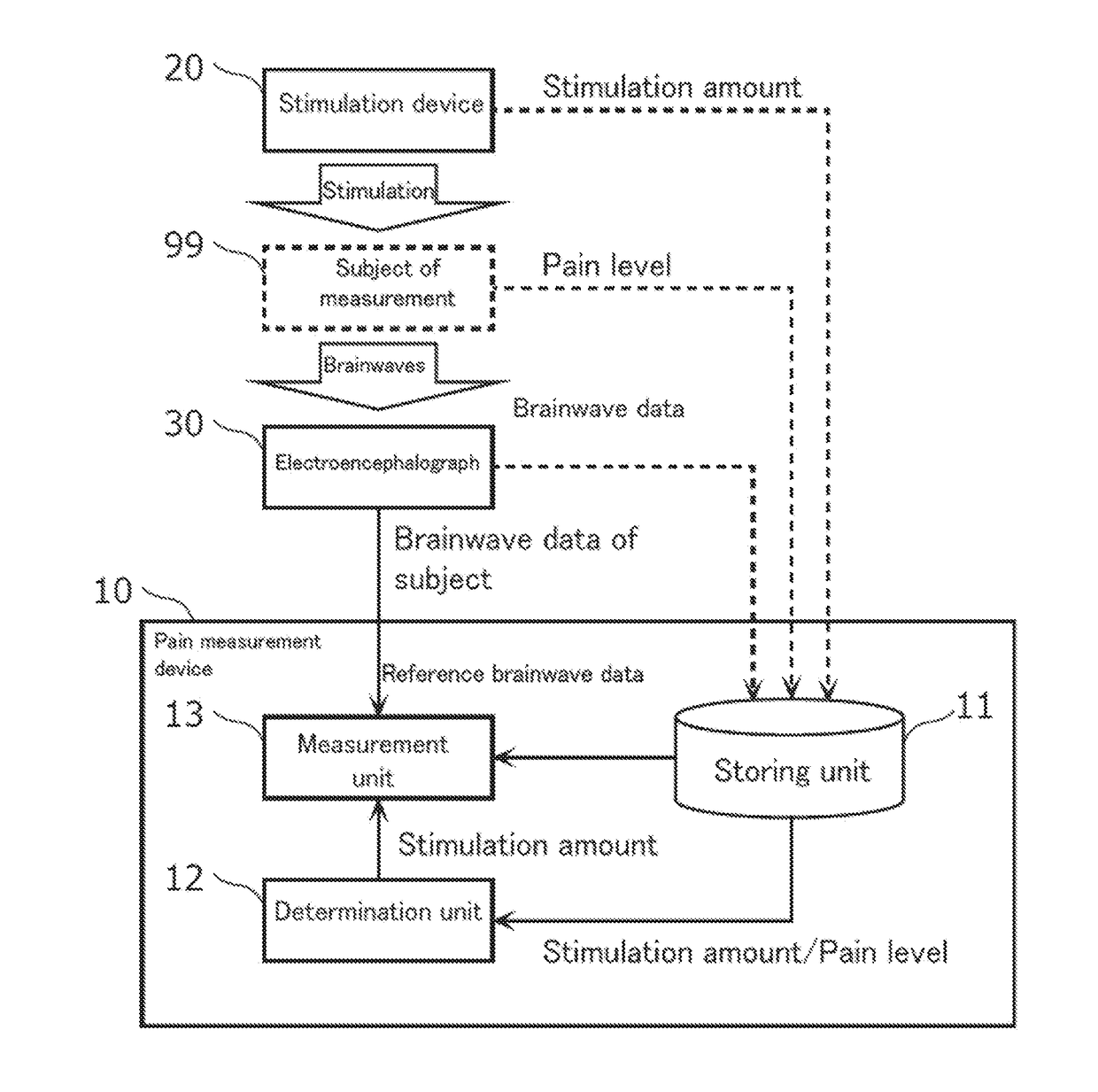
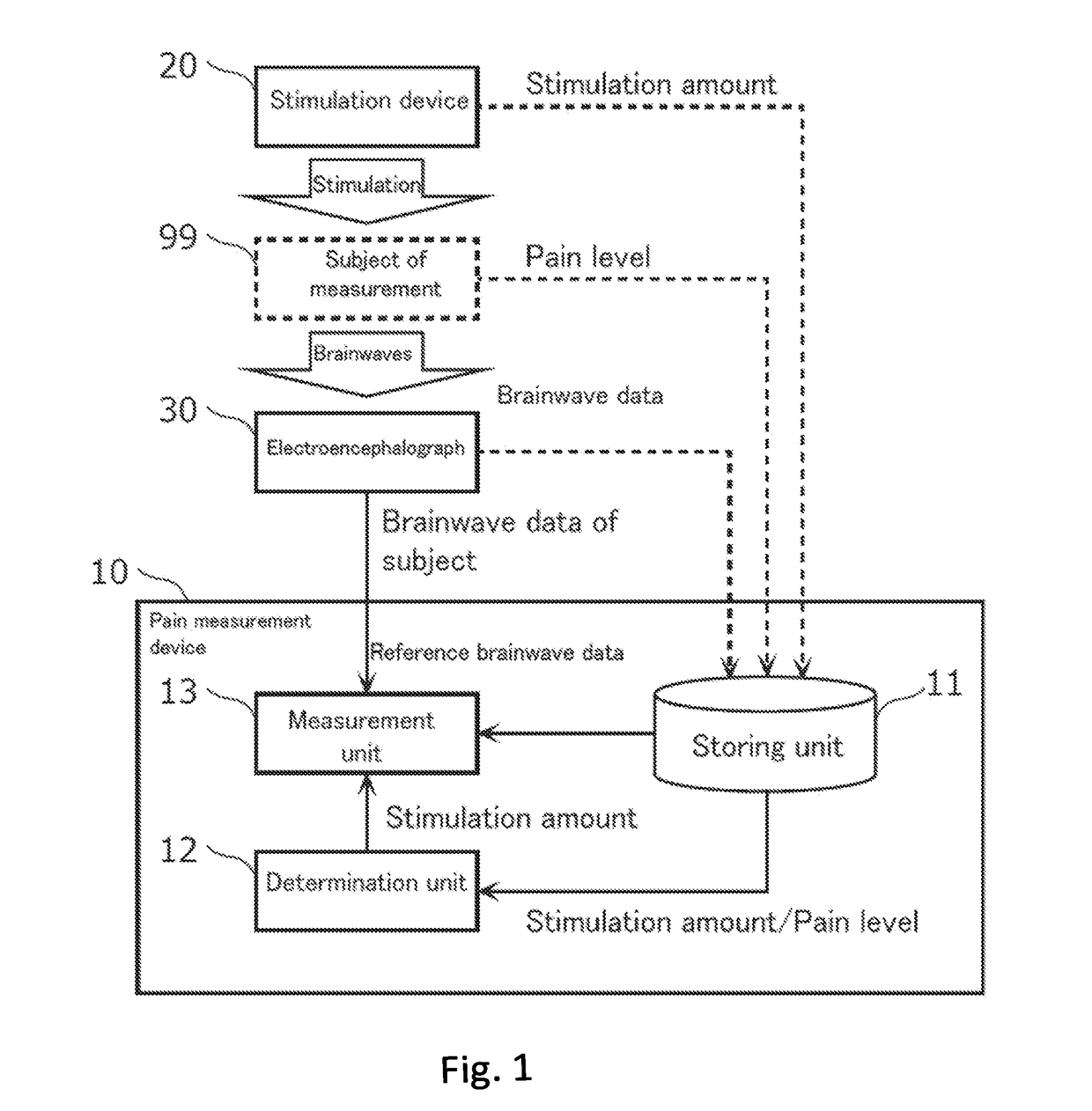
[0037]FIG. 1 is a block diagram showing the configuration of the pain measurement system in Embodiment 1. The pain measurement system comprises a pain measurement device 10, a stimulation device 20, and an electroencephalograph 30.

[0038]The pain measurement device 10 measures pain being experienced by a subject of measurement 99. A subject of measurement is a living body in which pain induces a change in brainwaves. A subject of measurement does not need to be limited to humans.

[0039]The stimulation device 20 applies stimulations at a plurality of stimulation amounts individually to the subject of measurement 99. Specifically, the stimulation device 20 applies, for example, a plurality of stimulations in order while changing the stimulation amount to the subject of measurement 99.

[0040]In this regard, a stimulation is applied to the subject of measurement 99 from the outside of the subject of measurement 99 to induce pain of various levels t...

embodiment 2

[0088]Next, Embodiment 2 is explained. This embodiment is different from the above-described Embodiment 1 in that a pain level and brainwave data corresponding to a stimulation amount that is not actually applied to a subject of measurement are estimated, and the result of estimation is used to determine a baseline stimulation amount. This embodiment is explained hereinafter mainly with respect to the above-described difference from Embodiment 1.

[Configuration of Pain Measurement System]

[0089]FIG. 6 is a block diagram showing a configuration of the pain measurement system in Embodiment 2. In FIG. 6, constituent elements that are substantially the same as FIG. 1 are assigned with the same symbol, and explanation thereof is omitted when appropriate. The pain measurement system according to this embodiment comprises a pain measurement device 10A, a stimulation device 20, and an electroencephalograph 30.

[0090]The pain measurement device 10A measures pain being experienced by a subject o...


PUM


Abstract

This pain measurement device (10) for measuring pain experienced by a subject (99) is provided with a determination unit (12) for determining a reference stimulation intensity corresponding to reference pain of the subject (99), on the basis of a relationship between pain levels reported by the subject (99) and stimulation intensities applied to the subject (99), and a measurement unit (13) which compares electroencephalographic data measured from the subject (99) and reference electroencephalographic data corresponding to the reference stimulation intensity to measure pain experienced by the subject (99) when the electroencephalographic data is measured.

Description

TECHNICAL FIELD[0001]The present invention relates to a pain measurement device for measuring pain being experienced by a subject of measurement, based on brainwave data of the subject of measurement.BACKGROUND ART[0002]While pain is fundamentally subjective, objective evaluation thereof is desired for treatment. Patients often suffer disadvantages by underestimating pain. In this regard, methods for objective measurement of pain have been proposed (see, for example, Patent Literature 1).CITATION LISTPatent Literature[0003][PTL 1] Japanese National Phase PCT Laid-open Publication No. 2010-523226SUMMARY OF INVENTIONTechnical Problem[0004]However, the above-described conventional techniques cannot correctly measure pain in some cases due to individual differences in subjects of measurement.[0005]In this regard, the present invention provides a pain measurement device that can objectively and highly precisely measure pain being experienced by a subject of measurement.Solution to Proble...

Claims


Application Information

Patent Timeline
IPC IPC(8): A61B5/00A61B5/0484
CPCA61B5/4824A61B5/0484A61B10/00A61B5/4827A61B5/377A61B5/369
Inventor NAKAE, AYA
Owner OSAKA UNIV
Why Eureka
Try Eureka