
Surgical Instrument With Articulation Region

a surgical instrument and articulation technology, applied in the field of surgical instruments, can solve the problems of added morbidity, surgeons lack of tools, and the inability to adapt to many applications of hinge joints

Active Publication Date: 2018-08-30
STRYKER CORP
View PDF6 Cites 294 Cited by
  • Summary
  • Abstract
  • Description
  • Claims
  • Application Information

AI Technical Summary

Benefits of technology

The present invention provides a surgical instrument with an articulating tube assembly that allows for movement of the inner and outer tubes in relation to the articulating region, resulting in a single plane of articulation. The instrument also includes an actuation assembly for moving the inner and outer tubes, an articulation region, and a viewing and illumination assembly for better visualization and illumination of the distal end of the instrument. The method of operating the instrument involves using the actuation assembly to move the inner and outer tubes in relation to the articulating region. The technical effects of this invention include improved precision and control during surgical procedures, as well as improved visualization and illumination for the surgeon.

Problems solved by technology

This added morbidity is because the surgeons do not have tools that enable them to visualize or remove the impingement any other way.
While suitable for some applications, a hinge joint is not suitable for many applications such as those which require tissue extraction or rotary or reciprocating power transmission through a region of articulation.
Many of these devices available today are extremely complicated assemblies with dozens of tiny moving parts, requiring painstaking assembly and considerable expense to maintain.
One limitation to such multi-segment articulation devices is their lack of stiffness.
This type of “snaking” movement is acceptable in certain application such as steerable endoscopes or steering catheters, but in others such as power-tool applications such as shavers or burs, such movement would result in highly undesirable poor control and stability.
Further, during arthroscopic surgery, there are occasions where bone needs to be removed from an area of anatomy of the patient that is difficult to access using a straight tool.
For example, during an Anterior Interior Illicac Spine (AIIS) pincer removal in the hip, it can be difficult to access the AIIS region using traditional hip arthroscopy portal placements and straight tools.
Additionally, the Psoas canal region of the hip is difficult to access using a straight tool.
However, angled burs are difficult to almost impossible to insert down a standard hip arthroscopy cannula depending on the degree of angle of the tool.
In addition, line of sight is a common limitation in the surgical field.
This enlarging of the surgical site results in significant collateral damage, pain, and longer recovery times for the patient.
In many situations, as a surgical instrument is introduced to the surgical site, the distal end of the instrument, and the tissue it contacts, is not visible to the surgeon because the instrument itself obstructs the surgeon's view.
Curved instruments and articulating instruments are capable of reaching and working around corners, but because the surgeon's line of sight is limited to a straight line, the safety and effectiveness of these tools is limited.

Method used


Image

  • Surgical Instrument With Articulation Region
  • Surgical Instrument With Articulation Region
  • Surgical Instrument With Articulation Region

Examples


Embodiment Construction

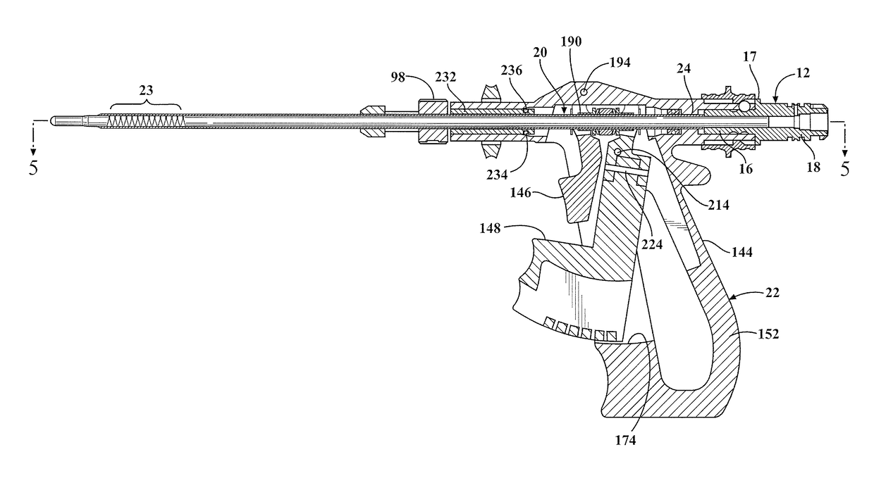
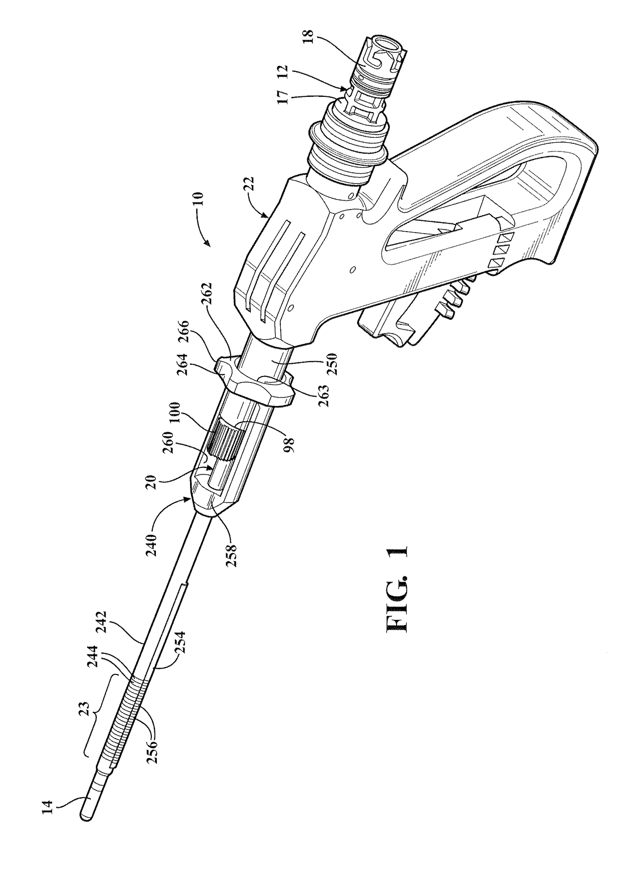
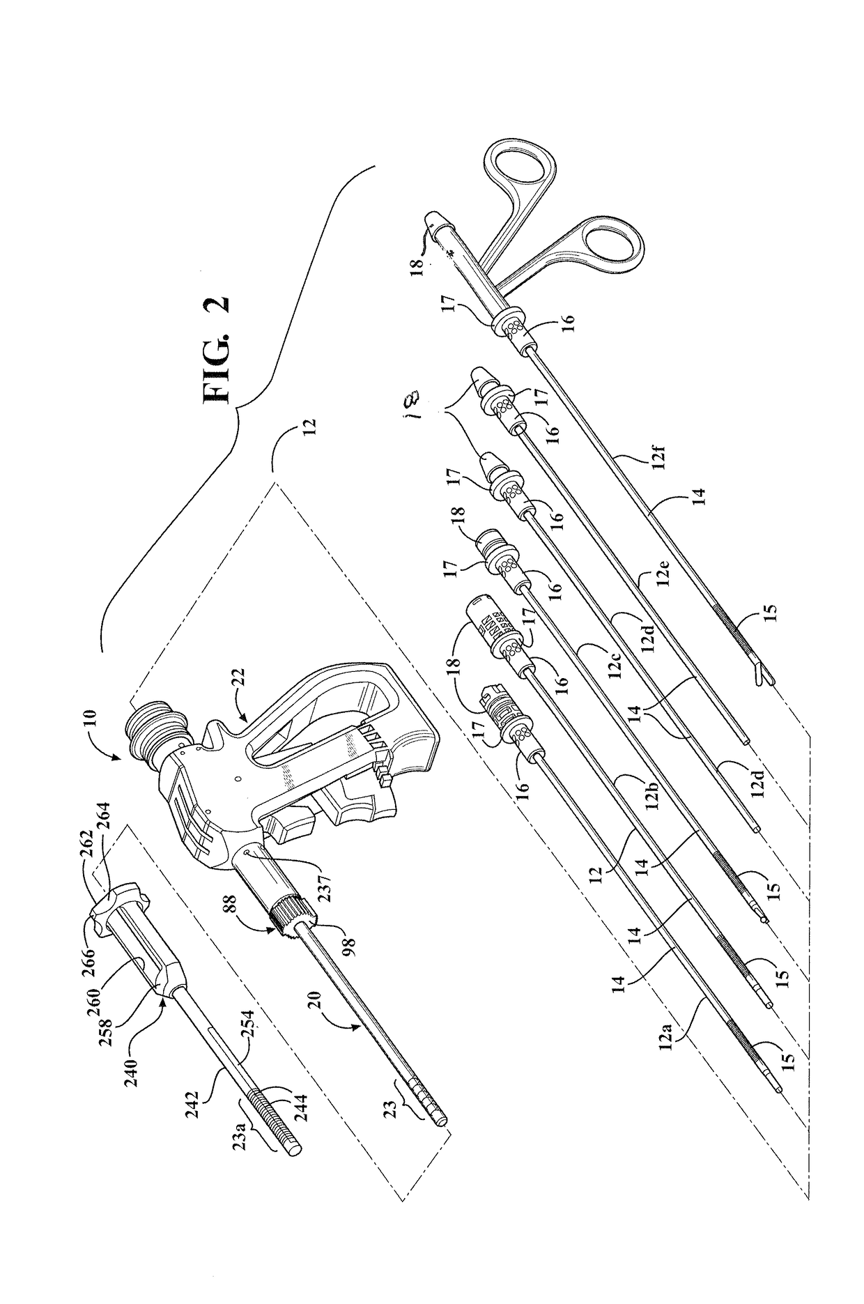
[0067]Referring to FIGS. 1 and 2, a surgical instrument 10, according to the present invention, is shown for use in a medical procedure for a patient (not shown). As illustrated in FIG. 2, the surgical instrument 10 is used with one or more working tools 12. The surgical instrument 10 is capable of receiving and releaseably securing one of the working tools 12.

[0068]Exemplary working tools 12 may be a flexible bur 12a, a flexible bur 12b, a flexible high speed bur 12c, a flexible suction device 12d, a flexible internal imaging and suction device 12e, and / or a flexible manual instrument 12f such as graspers, bipolar forceps, etc. Powered tissue devices 12a, 12b, and 12c and manual instrument 12f comprise a shaft portion 14 and a local flexible region 15 along the shaft portion 14 near a distal end. The flexible suction device 12d and flexible internal imaging and section device 12e of the working tools 12 are devices that are configured to flex along at least a portion, of the entire...


PUM


Abstract

A surgical instrument (10, 110, 210) includes an articulating tube assembly (20, 120, 220) having a proximal end and a distal end, an articulating region (23, 123, 223) disposed between the proximal end and the distal end, and a proximal axis axially extending from the proximal end to the articulating region (23, 123, 223). The articulating tube assembly (20, 120, 220) includes an inner tube (24, 124, 224) and an outer tube (26, 126, 226) each having the articulating region (23, 123, 223). The inner tube (24, 124, 224) and the outer tube (26, 126, 226) being movable relative to each other proximal to the articulating region (23, 123, 223) and fixed axially relative one another distal to the articulating region (23, 123, 223). The surgical instrument (10, 110, 210) also includes an actuation assembly (22, 122, 222a) coupled to the articulating tube assembly (20, 120, 220) for moving the inner tube (24, 124, 224) and the outer tube (26, 126, 226) axially relative to each other for articulating the articulating region (23, 123, 223) of the articulating tube assembly (20, 120, 220) between a first configuration and a second configuration, wherein the articulating region (23, 123, 223) is rigid in the first configuration and the second configuration.

Description

CROSS-REFERENCE TO RELATED APPLICATION(S)[0001]The present application claims the benefit of U.S. Provisional Patent Application Nos. 62 / 121,265 and 62 / 121,080, both filed Feb. 26, 2015, the entire disclosure of each is hereby incorporated by reference.TECHNICAL FIELD[0002]The present invention relates generally to surgical instruments and, more particularly to, a surgical instrument with tube articulation and illumination for use on patients.BACKGROUND[0003]It is known that medical practitioners have found it useful to use surgical instruments to assist in the performance of surgical procedures. A surgical instrument is designed to be applied to a surgical site on the patient. The practitioner is able to position the surgical instrument at the site on the patient at which the instrument is to perform a medical or surgical procedure. Today many procedures such a lateral and central foramenal decompression must be performed by removing considerable healthy tissue, specifically the la...

Claims


Application Information

Patent Timeline
Patent Type & Authority Applications(United States)
IPC IPC(8): A61B17/00
CPCA61B17/00234A61B2217/005A61B17/29A61B18/1445A61B2018/00982A61B17/1659A61B17/8875A61B2017/00367A61B17/32002A61B17/3421A61B2017/00314A61B2017/00477A61B1/317A61M25/0138A61M25/0147A61B2017/00309A61B2017/2905A61B2017/2908A61B2017/2927A61B17/1631A61B17/320758A61B2017/22079A61B2017/320032A61B17/1622A61B1/0051A61B1/0055A61B1/0056A61B1/005
Inventor WALEN, JAMES G.DEENY, BRYAN G.NUNAN, GERARD
Owner STRYKER CORP
Learn More