Shunt for redistributing atrial blood volume

a technology of atrial blood volume and shunt, which is applied in the field of percutaneous placement of implants, can solve the problems of substantial fall in lv end-diastolic pressure, and achieve the effect of reducing the risk of paradoxical embolism and maintaining luminal patency

Active Publication Date: 2018-08-30
WAVE LTD V
View PDF0 Cites 43 Cited by
  • Summary
  • Abstract
  • Description
  • Claims
  • Application Information

AI Technical Summary

Benefits of technology

[0069]In view of the foregoing drawbacks of previously-known interatrial shunts, a shunt constructed in accordance with the principles of the present invention provides a more durable configuration that maintains luminal patency for exte...

Problems solved by technology

Accordingly, even a modest reduction in LV end-diastolic ...

Method used


Image

  • Shunt for redistributing atrial blood volume
  • Shunt for redistributing atrial blood volume
  • Shunt for redistributing atrial blood volume

Examples


Embodiment Construction

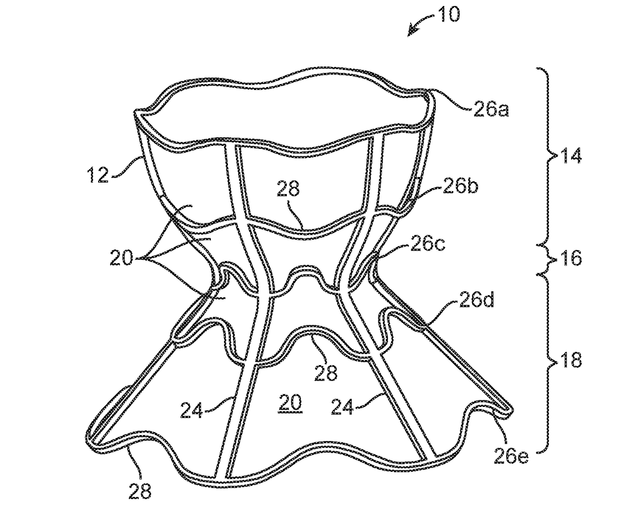
[0095]Interatrial shunts are provided for redistributing interatrial blood volumes and reducing left atrial pressure, which may be advantageous in treating subjects suffering from heart failure (HF) or other disorders associated with elevated left atrial pressure. A preferred embodiment of the inventive device includes an anchor, which may be an hourglass or “diabolo” shaped stent or frame, and a conduit, formed by encapsulating the frame in a synthetic biocompatible material. The shunt is configured to be lodged securely within a passage formed in the atrial septum, preferably the fossa ovalis, and provides one-way blood flow from the left atrium to the right atrium, when blood pressure in the left atrium exceeds that on the right.

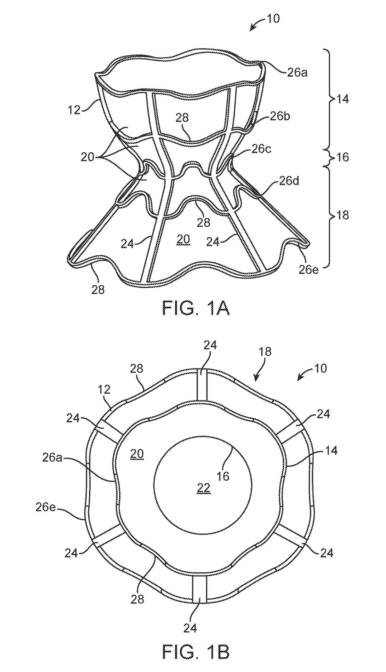
[0096]Referring now to FIGS. 1A to 1C, an illustrative embodiment of shunt 10 of the present invention is described. Shunt 10 generally comprises anchor 12 having three regions: flared or funnel-shaped end region 14, flared or funnel-shaped end region 18,...


PUM


Abstract

A shunt for regulating blood pressure between a patient's left atrium and right atrium comprises an anchor comprising a neck region, first and second end regions, and a conduit affixed with the anchor that formed of a biocompatible material that is resistant to transmural and translation tissue ingrowth and that reduces a risk of paradoxical embolism.

Description

FIELD OF THE INVENTION[0001]This application generally relates to percutaneously placed implants and methods for redistributing blood from one cardiac chamber to another to address pathologies such as heart failure (HF), myocardial infarction (MI) and pulmonary arterial hypertension (PAH).BACKGROUND OF THE INVENTION[0002]Heart failure is the physiological state in which cardiac output is insufficient to meet the needs of the body or to do so only at a higher filing pressure. There are many underlying causes of HF, including myocardial infarction, coronary artery disease, valvular disease, hypertension, and myocarditis. Chronic heart failure is associated with neurohormonal activation and alterations in autonomic control. Although these compensatory neurohormonal mechanisms provide valuable support for the heart under normal physiological circumstances, they also play a fundamental role in the development and subsequent progression of HF.[0003]For example, one of the body's main comp...

Claims


Application Information

Patent Timeline
IPC IPC(8): A61F2/01A61F2/24A61M27/00
CPCA61F2/01A61F2/2478A61F2002/249A61F2250/0098A61F2250/0051A61M27/002A61F2/2487
Inventor EIGLER, NEALROSEN, LIORHAFELFINGER, WERNERROZENFELD, EREZBEN-DAVID, TAMIRNAE, NIRYACOBY, MENASHENITZAN, YAACOV
Owner WAVE LTD V
Why Eureka
Try Eureka