
Devices and methods for providing passage between heart chambers

a technology of heart chamber and device, applied in the field of devices, can solve the problems of insufficient cardiac output, pulmonary venous hypertension and lung edema, and insufficient heart rate, and achieve the effect of maintaining luminal patency

Pending Publication Date: 2021-04-29
WAVE LTD V
View PDF2 Cites 6 Cited by
  • Summary
  • Abstract
  • Description
  • Claims
  • Application Information

AI Technical Summary

Benefits of technology

The present invention provides an adjustable passage device that overcomes the shortcomings of previous shunt devices. The device is more durable and can maintain luminal patency for longer periods of time. It allows for the selection of desired passage diameters for catheterization tools, as well as inlet and outlet diameters and angles that conform to various tissue geometries between adjacent body cavities, thereby securely anchoring the device within the tissue.

Problems solved by technology

Heart failure is the physiological state in which cardiac output is insufficient to meet the needs of the body or to do so only at a higher filling pressure.
This stiffness may impede blood from filling the heart and produce backup into the lungs, which may result in pulmonary venous hypertension and lung edema.
Such mechanical devices enable propulsion of significant volumes of blood (liters / min), but are limited by a need for a power supply, relatively large pumps, and pose a risk of hemolysis, thrombus formation, and infection.
These include severe shortness of breath, pulmonary edema, hypoxia, the need for acute hospitalization, mechanical ventilation, and death.
In addition, following implantation of a shunt device within a heart wall, tissue ingrowth including an endothelial layer or neointima layer typically forms on the device, thereby inhibiting thrombogenicity of the shunt device, and narrowing the size of the passage through the device.

Method used


Image

  • Devices and methods for providing passage between heart chambers
  • Devices and methods for providing passage between heart chambers
  • Devices and methods for providing passage between heart chambers

Examples


Embodiment Construction

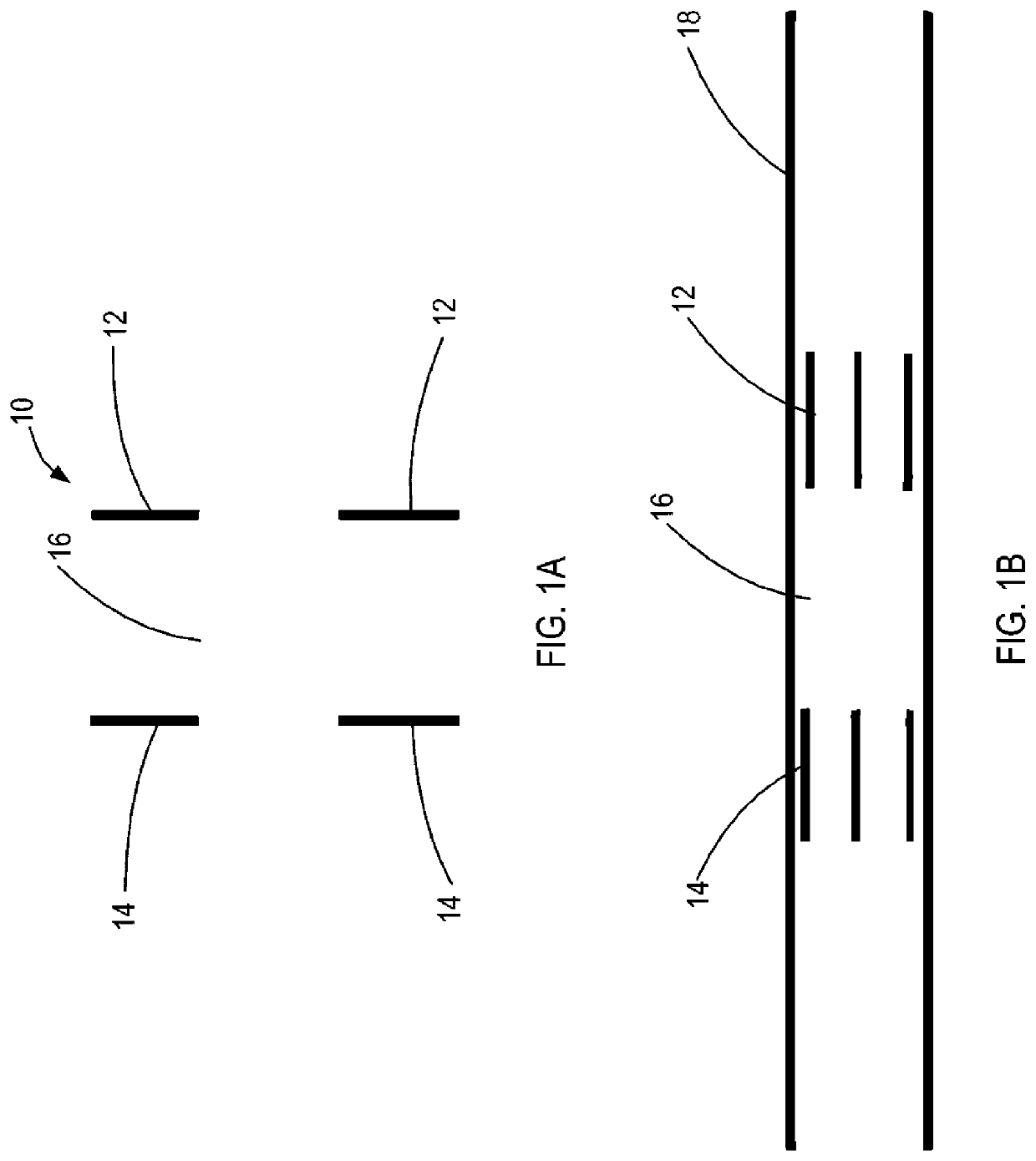
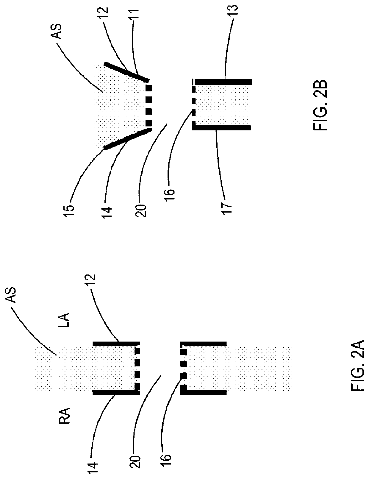
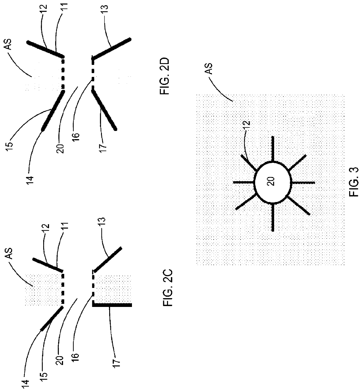
[0048]Devices are provided for providing a passage between adjacent body cavities, e.g., hearth chambers, within a patient. The diameter of the passage through the device may be adjusted accordingly responsive to the needs of the clinical procedure through the passage. In addition, the angles and cross-sectional areas of the proximal and distal end regions of the device may be independently selected to secure the device within the tissue, e.g., heart wall, and to selectively control the flowrate through the device responsive to the pressure gradient across the device. Further, the device may be designed to anchor an additional medical device within the heart wall, such as a septal occluder, an open atrial septal shunt, a valved atrial septal shunt, a left atrial blood pressure sensor, or a blood pump.

[0049]Referring now to FIGS. 1A and 1B, an exemplary passage device is provided. Passage device 10 includes first end region 12, second end region 14, and middle region 16 extending bet...


PUM


Abstract

A device for providing a passage between a first and second heart chamber is provided. The device includes a middle region having first and second ends, a lumen extending therethrough having a longitudinal axis, a first end region coupled to the first end, and a second end region coupled to the second end. The first end region may be delivered in the first heart chamber in a compressed state and transitioned to a deployed state, the first end region being deformable such that portions of the first end region are expandable to different angles relative to the longitudinal axis. The second end region may be delivered in the second heart chamber in a compressed state and transitioned to a deployed state therein, the second end region being deformable such that portions of the second end region are expandable to different angles relative to the longitudinal axis.

Description

CROSS-REFERENCE TO RELATED APPLICATIONS[0001]This application claims priority to U.S. Patent Provisional Application Ser. No. 62 / 619,748, filed Jan. 20, 2018, the entire contents of which are incorporated by reference herein.FIELD OF THE INVENTION[0002]This application generally relates to percutaneously placed implants and methods for providing a passage between body cavities, e.g., heart chambers, to address pathologies such as heart failure (“HF”), myocardial infarction (“MI”) and pulmonary arterial hypertension (“PAH”), and to provide access to a surgeon's tool between the heart chambers.BACKGROUND OF THE INVENTION[0003]For a number of medical conditions, there is benefit in creating and / or maintaining a passage between two body cavities. Such a passage is typically used in catheterization procedures where the catheter is delivered through a patient's vasculature. In some catheterization procedures, there is a benefit in moving from one cavity to another cavity by creating a pas...

Claims


Application Information

Patent Timeline
IPC IPC(8): A61B17/11A61B17/00
CPCA61B17/11A61B17/0057A61B2017/00084A61B2017/00243A61B2017/00358A61B2562/0247A61B2017/00592A61B2017/00606A61B2017/00623A61B2017/1107A61B2017/1139A61B2017/00106A61B5/6852A61B5/6869A61B5/0215A61B5/026A61F2/2418A61M25/1002A61B2017/00022A61B2017/00575A61M60/861A61M60/165
Inventor BEN-DAVID, TAMIREIGLER, NEALNAE, NIRROSEN, LIORROZENFELD, EREZWHITING, JAMES S.
Owner WAVE LTD V
Learn More