Asymmetric shunt for redistributing atrial blood volume

a shunt and atrial blood technology, applied in the field of percutaneous placement of asymmetric implants, can solve the problems of paradoxical embolism, insufficient cardiac output, and enlarged heart muscle, especially ventricles, and achieve the effects of maintaining luminal patency, reducing the risk of paradoxical embolism, and being durabl

Active Publication Date: 2022-04-05
WAVE LTD V
View PDF527 Cites 10 Cited by
  • Summary
  • Abstract
  • Description
  • Claims
  • Application Information

AI Technical Summary

Benefits of technology

[0072]In view of the foregoing drawbacks of previously-known interatrial shunts, an asymmetric shunt constructed in accordance with the principles of the present invention provides a more durable configuration that maintains luminal patency for extended periods of time. The inventive asymmetric shunts further enable redistribution of interatrial blood volumes and pressure imbalances while reducing a risk of paradoxical embolism caused by emboli moving through the shunt from the right to left atria.
[0075]In addition, the asymmetric device may include a conduit having a lumen wall defining a lumen, wherein the lumen wall is resistant to transmural and translational tissue growth. For example, the lumen may have a diameter in the neck region in a range of 5 mm to 6.5 mm, and may provide high velocity flow therethrough, while limiting paradoxical emboli passing across the lumen during a transient pressure gradient reversal. The conduit may include a layer of biocompatible material. The conduit may have a first end that extends from the neck region a first distance of at least 3 mm into the patient's left atrium and a second end that extends from the neck region a second distance of at least 3 mm into the patient's right atrium, thereby preventing pannus formation from narrowing the lumen of the conduit in the neck region. The second end of the conduit may extend from the neck region a distance of between 3 mm to 15 mm into the patient's right atrium.
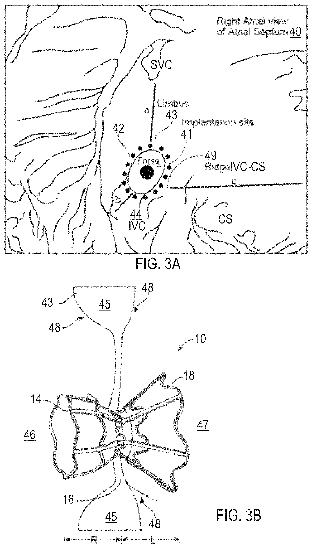
[0076]Further, the conduit may be sized and shaped so that when implanted the second end of the conduit is located out of a natural circulation flow path of blood entering into the patient's right atrium from an inferior vena cava, thereby reducing a risk of emboli entrained in flow from the inferior vena cava being directed into the second end of the conduit. In addition, the first expandable end region of the asymmetric device, in the expanded deployed state, may form a filter that prevents emboli from entering the second end of the conduit.

Problems solved by technology

Heart failure is the physiological state in which cardiac output is insufficient to meet the needs of the body or to do so only at a higher filing pressure.
However, the larger volumes of blood also cause the heart muscle, particularly the ventricles, to become enlarged.
In low ejection fraction (“EF”) heart failure, high pressures in the heart result from the body's attempt to maintain the high pressures needed for adequate peripheral perfusion.
However, as the heart weakens as a result of such high pressures, the disorder becomes exacerbated.
This stiffness may impede blood from filling the heart and produce backup into the lungs, which may result in pulmonary venous hypertension and lung edema.
Such mechanical devices enable propulsion of significant volumes of blood (liters / min), but are limited by a need for a power supply, relatively large pumps, and pose a risk of hemolysis, thrombus formation, and infection.
These include severe shortness of breath, pulmonary edema, hypoxia, the need for acute hospitalization, mechanical ventilation, and death.
Both shunts also have observed and theoretical drawbacks, which may limit their effectiveness and use.
Although relatively simple in theory and construction, orifice-plate mesh type shunts have several important drawbacks that are expected to reduce their overall potential for clinical safety and effectiveness.
A first drawback of orifice-plate devices is the susceptibility to narrow or close during the post-implantation healing period.
Such tissue ingrowth typically spreads over the surfaces of the implant's struts, mesh, or discs, and may substantially narrow the orifice lumen or even entirely occlude the shunt.
Narrowing or occlusion of the shunt prevents LA decompression and limits any positive effect for the patient.
Also, variability results from differences in host wound healing responses.
It was not reported whether the shunts were occluded or if the imaging study was simply too technically difficult to tell for certain.
Although additional interventional cardiology procedures may be undertaken to restore lost luminal patency, such procedures may pose unacceptable risks, including death and stroke from embolization of the orifice-clogging material, and there is no guarantee that the orifice will not occlude again.
A second drawback of an orifice-plate mesh shunt is the potential for paradoxical embolization.
Patients with transvenous endocardial pacing leads and an intracardiac shunt have a 3-fold increased risk of systemic thromboembolism, suggesting that paradoxical embolism is a contributing underlying cause.
The presence of an atrial septal aneurysm is an additional risk factor.
In this setting, interatrial electrical conduction delay results in retardation of LA contraction.
From these data, it seems reasonable to expect that an orifice-plate mesh shunt, by virtue of its anatomic similarities with congenital secundum ASD, would have a similar risk of paradoxical embolization.
A third drawback of an orifice-plate mesh shunt is that percutaneous removal of the shunt is only possible at the time of implantation.
Should the shunt become a nidus for infection, develop fatigue or corrosion fractures of its metallic framework, or erode or otherwise impinge on other vital cardiac structures, it cannot be removed by percutaneous retrieval / removal techniques.
Attempts at percutaneous removal may result in tearing of the septum, pericardial tamponade, and device embolization into the systemic circulation, resulting in death or the need for emergency surgery.
Performing such surgical procedures in patients with already established severe heart failure, including its frequently associated co-morbid conditions such as peripheral, cerebrovascular, and coronary artery disease, renal dysfunction, and diabetes, would be expected to have substantial risks for mortality or severe morbidity.
A fourth drawback of an orifice-plate mesh type of shunt is that its geometry renders it relatively inefficient in supporting high flow.
For any given pressure gradient across the shunt, an orifice-plate geometry requires a larger orifice because it has a reduced effective orifice size compared with other geometries, such as a venturi-shaped lumen, or a conical shaped nozzle.
This is because with an office-plate, there is more energy loss associated with eddy currents at the edges of the plate.
A fifth drawback of an orifice-plate mesh shunt is that it occupies a large area or footprint on the interatrial septum.
These flanges exert persistent pressure on the septum, causing injuring and stimulating an exaggerated healing response as described above.
Also, the rigidity of the mesh may interfere with the normal motion of the muscular septum.
Such erosion has been associated with severe complications including cardiac tamponade and death.
For example, the similarly sized Amplatzer ASD disc occlusion device described above has been occasionally associated with erosion into adjoining tissues with resulting catastrophic outcomes.
Additional issues associated with placing relatively large devices with complex three-dimensional geometries are potential difficulties in positioning the shunts accurately in the FO, obtaining sufficient tissue anchoring to prevent migration, and having devices conform to irregularities of the cardiac anatomy.
For example, in a report of attempted implantation of orifice-plate mesh shunts in 66 patients in the above cited publication authored by Hasenfuss, et al., device placement was not possible in two patients.
Finally, the large footprint on the atrial septum may hinder or render impossible performing other interventional procedures that require transseptal access.
Other structural heart disease procedures that have large diameter delivery systems and / or require crossing the FO in specific locations may encounter difficulties or simply not be possible.
These factors have also been associated with poor outcomes.
This observation gives rise to concern about a decrease in the clinical effectiveness of the shunts over time
For example, it is possible that contraction of pannus tissue formed during the later stages of healing (remodeling) could result in extrinsic compression of the shunt.
However, there is no evidence to support this scenario based on multiple observations of frame geometry seen during pre-clinical studies and during follow-up transesophageal echocardiography (“TEE”), CT, or fluoroscopic imaging in humans.
These data indicate that when tissue coverage exceeds this thickness, the tissue interferes with fluid pressure measurement.
Although animal models of cardiovascular devices are limited in their ability to represent human tissue healing responses, the major differences are characteristically limited to the temporal duration of the response.
Although this shunt was patent, it would have been incompetent, allowing bidirectional flow, and would have shunted less than half of the flow expected for any given pressure gradient.

Method used


Image

  • Asymmetric shunt for redistributing atrial blood volume
  • Asymmetric shunt for redistributing atrial blood volume
  • Asymmetric shunt for redistributing atrial blood volume

Examples


Embodiment Construction

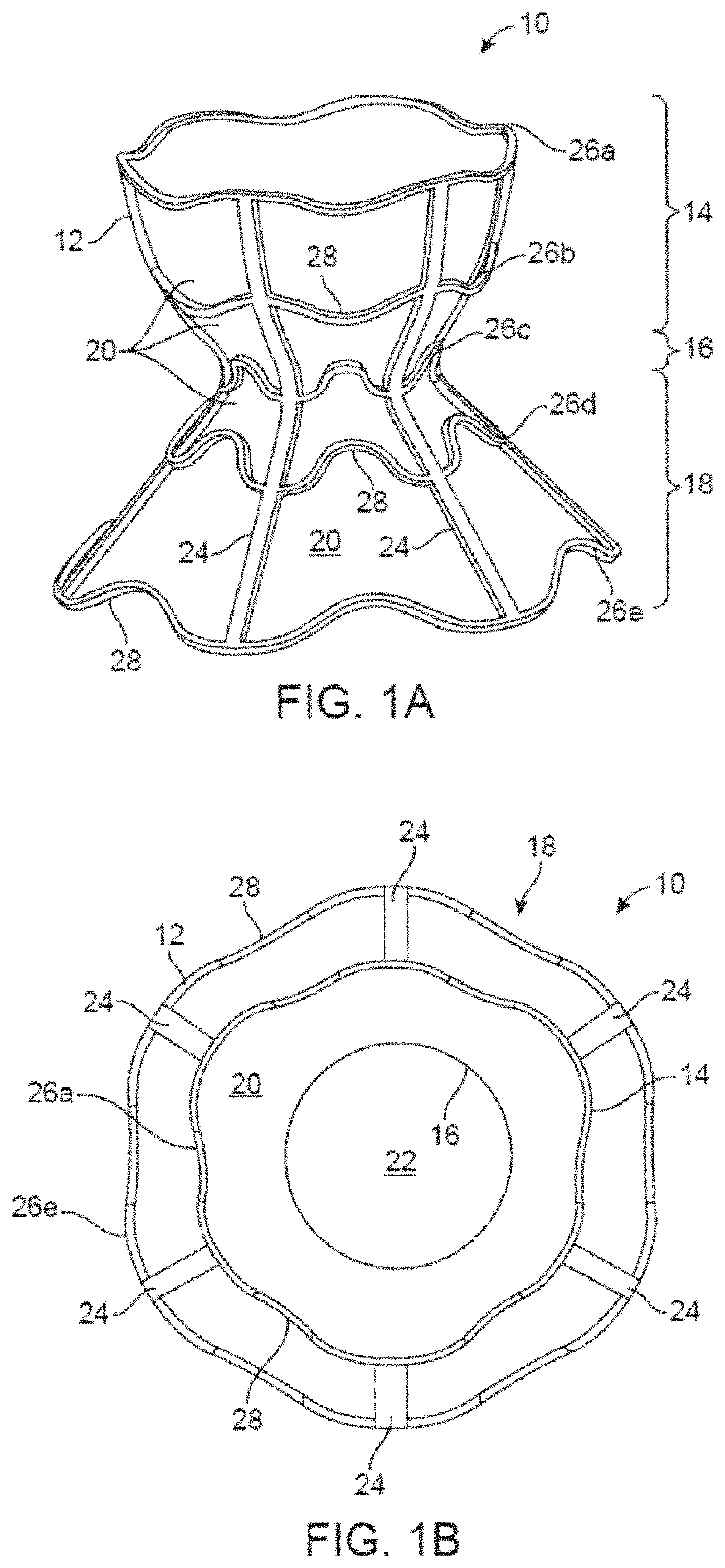
[0091]Interatrial shunts are provided for redistributing interatrial blood volumes and reducing left atrial pressure, which may be advantageous in treating subjects suffering from heart failure (“HF”) or other disorders associated with elevated left atrial pressure. A preferred embodiment of the inventive device includes an anchor, which may be an hourglass or “diabolo” shaped stent or frame, and a conduit, formed by encapsulating the frame in a synthetic biocompatible material. The shunt is configured to be lodged securely within a passage formed in the atrial septum, preferably the fossa ovalis, and provides one-way blood flow from the left atrium to the right atrium, when blood pressure in the left atrium exceeds that on the right.

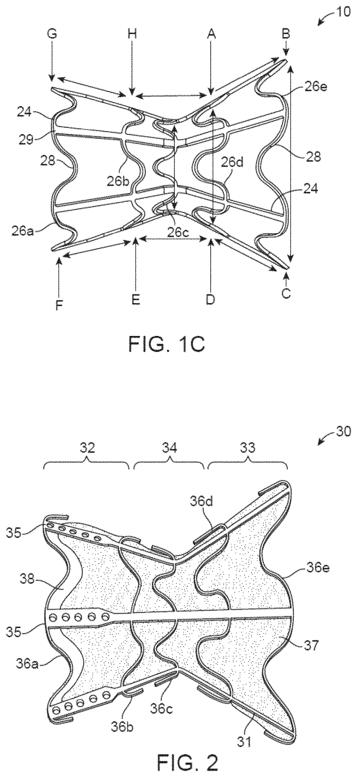
[0092]Referring now to FIGS. 1A to 1C, an illustrative embodiment of an interatrial shunt is described. Shunt 10 may be constructed similar to the shunt designs disclosed in U.S. Pat. No. 10,076,403, assigned to the assignee of the instant application, ...


PUM


Abstract

An asymmetric device for regulating blood volume distribution across a patient's atrial septum having a first expandable end region and a second expandable end region. The first expandable end region is transitionable from a contracted delivery state to an expanded deployed state in which the first expandable end region extends into the patient's left atrium and an inlet end of the first expandable end region is in a first plane. The second expandable end region is transitionable from a contracted delivery state to an expanded deployed state in which the second expandable end region extends into the patient's right atrium and an outlet end of the second expandable end region is in a second plane, such that the first plane intersects the second plane. The device further includes a neck region joining the first expandable end region to the second expandable end region, wherein the neck region is sized and shaped for placement in the patient's atrial septum.

Description

CROSS-REFERENCE TO RELATED APPLICATIONS[0001]This application is a continuation-in-part application of U.S. patent application Ser. No. 16 / 130,988, filed Sep. 13, 2018, which is a continuation of U.S. patent application Ser. No. 15 / 449,834, filed Mar. 3, 2017, now U.S. Pat. No. 10,076,403, the entire contents of each of which are incorporated by reference herein.FIELD OF THE INVENTION[0002]This application generally relates to percutaneously placed asymmetric implants and methods for redistributing blood from one cardiac chamber to another to address pathologies such as heart failure (“HF”), myocardial infarction (“MI”) and pulmonary arterial hypertension (“PAH”). BACKGROUND OF THE INVENTION[0003]Heart failure is the physiological state in which cardiac output is insufficient to meet the needs of the body or to do so only at a higher filing pressure. There are many underlying causes of HF, including myocardial infarction, coronary artery disease, valvular disease, hypertension, and ...

Claims


Application Information

Patent Timeline
Patent Type & Authority Patents(United States)
IPC IPC(8): A61M27/00A61F2/01A61F2/24A61F2/91
CPCA61M27/002A61F2/01A61F2/2487A61F2/91A61F2002/249A61F2230/001A61F2230/0013A61F2230/0054A61F2250/0039A61F2250/0051A61F2250/0098
Inventor EIGLER, NEALWHITING, JAMESNAE, NIR
Owner WAVE LTD V
Why Eureka
Try Eureka