Shunt for redistributing atrial blood volume

a technology of atrial blood volume and shunt, which is applied in the field of percutaneous placement of implants, can solve the problems of substantial fall in lv end-diastolic pressure, and achieve the effect of reducing the risk of paradoxical embolism and maintaining luminal patency

Active Publication Date: 2019-01-17
WAVE LTD V
View PDF0 Cites 44 Cited by
  • Summary
  • Abstract
  • Description
  • Claims
  • Application Information

AI Technical Summary

Benefits of technology

The present invention provides a durable interatrial shunt that maintains luminal patency for extended periods of time and reduces the risk of paradoxical embolism. The shunt design also enhances safety by improving long-term patency and reducing the risk of pannus formation. The shunt is designed to control left atrial pressure and relieve pulmonary congestive symptoms by reducing the impact of the shunt's implantation in the interatrial septum. The device can be used for treating heart failure and pulmonary congestion by reducing left atrial pressure and left ventricular end-diastolic pressure. Other heart pathologies that may be treated include myocardial infarction.

Problems solved by technology

Accordingly, even a modest reduction in LV end-diastolic volume leads to a substantial fall in LV end-diastolic pressure.

Method used


Image

  • Shunt for redistributing atrial blood volume
  • Shunt for redistributing atrial blood volume
  • Shunt for redistributing atrial blood volume

Examples


Embodiment Construction

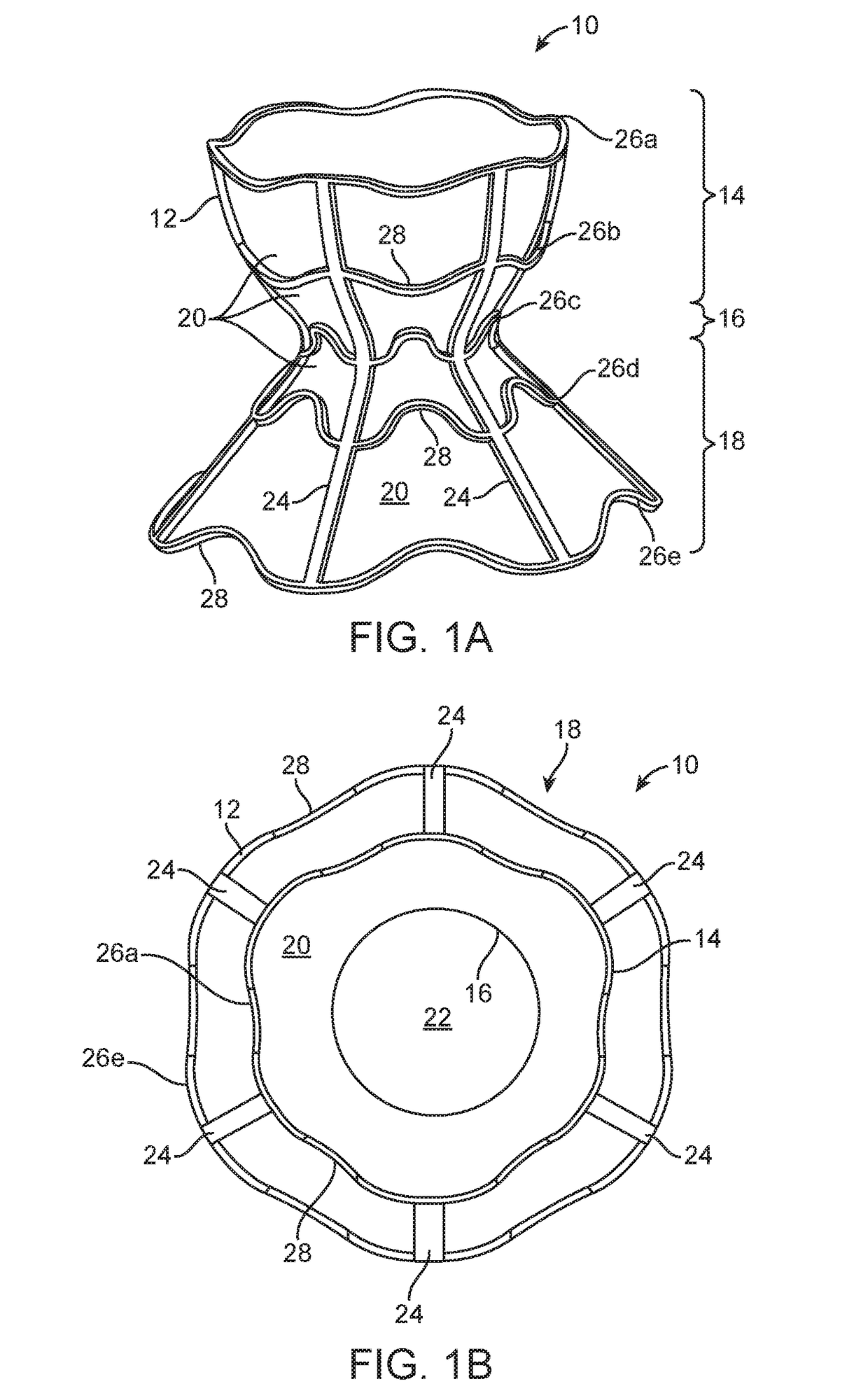
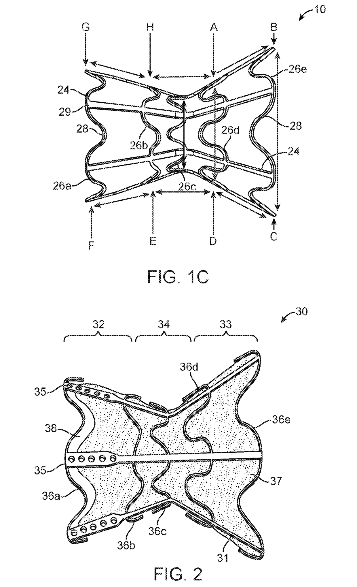
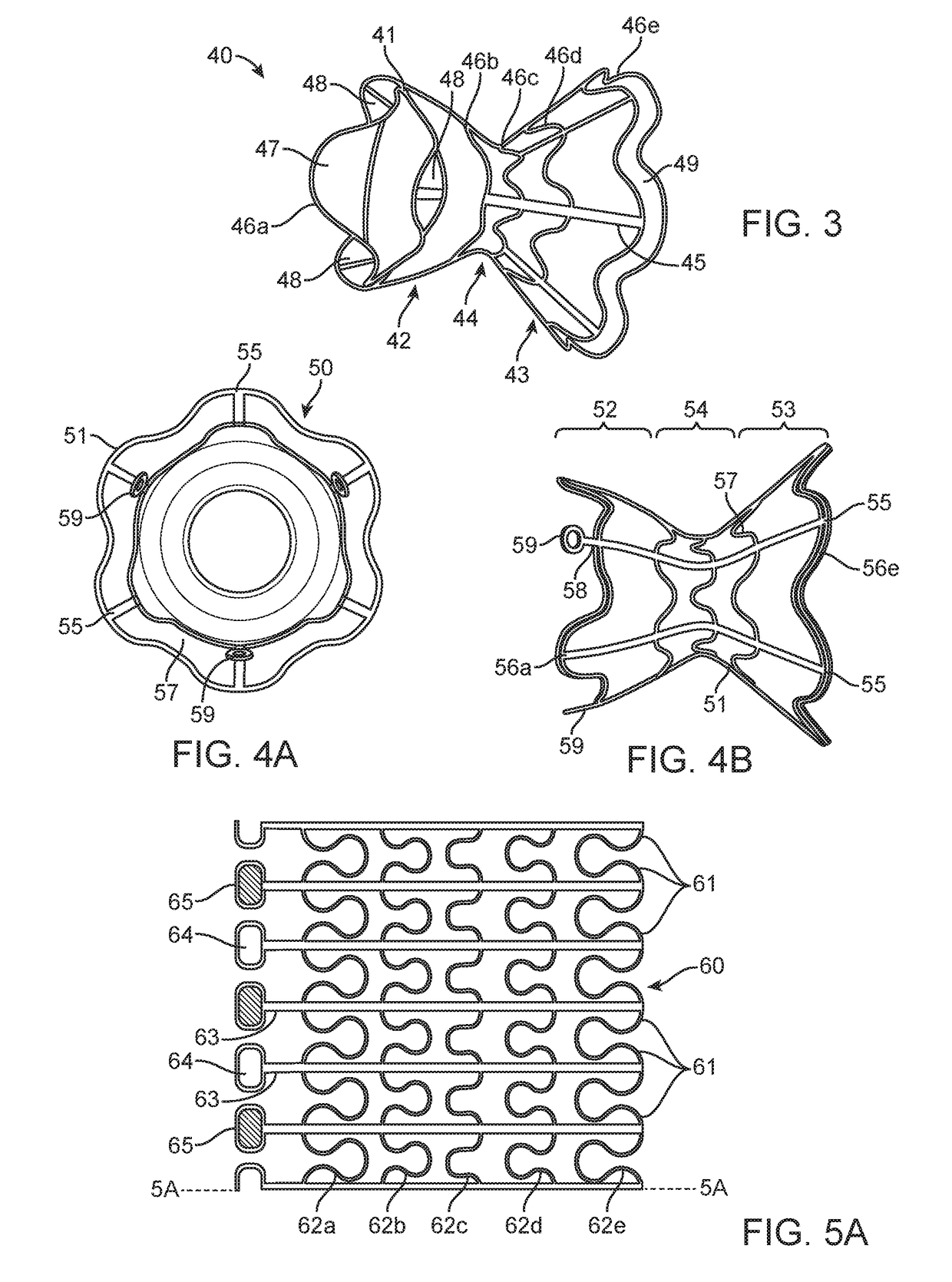
[0096]Interatrial shunts are provided for redistributing interatrial blood volumes and reducing left atrial pressure, which may be advantageous in treating subjects suffering from heart failure (HF) or other disorders associated with elevated left atrial pressure. A preferred embodiment of the inventive device includes an anchor, which may be an hourglass or “diabolo” shaped stent or frame, and a conduit, formed by encapsulating the frame in a synthetic biocompatible material. The shunt is configured to be lodged securely within a passage formed in the atrial septum, preferably the fossa ovalis, and provides one-way blood flow from the left atrium to the right atrium, when blood pressure in the left atrium exceeds that on the right.

[0097]Referring now to FIGS. 1A to 1C, an illustrative embodiment of shunt 10 of the present invention is described. Shunt 10 generally comprises anchor 12 having three regions: flared or funnel-shaped end region 14, flared or funnel-shaped end region 18,...


PUM


Abstract

A shunt for regulating blood pressure between a patient's left atrium and right atrium comprises an anchor comprising a neck region, first and second end regions, and a conduit affixed with the anchor that formed of a biocompatible material that is resistant to transmural and translation tissue ingrowth and that reduces a risk of paradoxical embolism.

Description

CROSS-REFERENCE TO RELATED APPLICATIONS[0001]This application is a continuation application of U.S. application Ser. No. 15 / 449,834, filed Mar. 3, 2017, now U.S. Pat. No. 10,076,403, which is a continuation-in-part application of U.S. application Ser. No. 14 / 712,801, filed May 14, 2015, now U.S. Pat. No. 9,980,815, which is a divisional application of U.S. application Ser. No. 13 / 193,335, filed Jul. 28, 2011, now U.S. Pat. No. 9,034,034, which claims the benefit of priority of U.S. Provisional Patent Application No. 61 / 425,792, filed Dec. 22, 2010, the entire contents of each of which are incorporated by reference herein. U.S. application Ser. No. 13 / 193,335 is also a continuation-in-part under 35 U.S.C. § 120 of International Patent Application No. PCT / IL2010 / 000354, filed May 4, 2010, which claims the benefit of U.S. Provisional Patent Application Nos. 61 / 175,073, filed May 4, 2009 and 61 / 240,667, filed Sep. 9, 2009, the entire contents of each of which are incorporated by referen...

Claims


Application Information

Patent Timeline
Patent Type & Authority Applications(United States)
IPC IPC(8): A61F2/01A61F2/24A61M27/00
CPCA61F2/2487A61M27/002A61F2002/249A61F2250/0051A61F2/01A61F2250/0098A61B2017/1139A61B2017/00243
Inventor EIGLER, NEALROSEN, LIORHAFELFINGER, WERNERROZENFELD, EREZBEN-DAVID, TAMIRNAE, NIRYACOBY, MENASHENITZAN, YAACOV
Owner WAVE LTD V
Why Eureka
Try Eureka