
Barrel stabilizing and recoil reducing muzzle brake

a technology which is applied in the field of barrel stabilization and muzzle brake, can solve the problems of reducing the control of the firearm, affecting the mechanism and mounting points holding the weapon, and reducing the shock force generated by the firearm recoil. it stabilizes the firearm, and reduces the recoil of the firearm

Active Publication Date: 2018-08-30
GRIFFITTS JAMES NORMAN
View PDF1 Cites 3 Cited by
  • Summary
  • Abstract
  • Description
  • Claims
  • Application Information

AI Technical Summary

Benefits of technology

The present invention is about a firearm that has a precision muzzle brake that reduces the recoil and stabilizes the firearm. This firearm is designed in a way that it controls the energy of the gas that comes out of the firearm and the gas produced by the burning propellant. The muzzle brake is advanced and precise, which makes it effective in reducing the recoil, deflection of the barrel, and lateral movements of the firearm.

Problems solved by technology

Over time, the shock force generated by firearm recoil can have a detrimental effect on the firearm and the optics or other sighting system used on the firearm.
Also, over time, the shock force generated by firearm recoil impacts the mechanism and mounting points holding the weapon.
This can be detrimental, for example, when a firearm is utilized in aircraft, mobile vehicles, or field mounted equipment.
Recoil also contributes directly to the reduced control of the firearm, and over time results in damage to the mounting arrangement, leading to eventual failure.
Movement of the firearm due to uncontrolled or poorly controlled recoil requires repositioning of the firearm and reacquisition of the target before another projectile can be fired.
While many prior art muzzle brakes of the type referenced above are known in the art, and while many such prior art muzzle brakes are capable of at least slightly reducing the negative effects of recoil in firearms, such prior art designs are limited in their ability to control or eliminate a substantial portion of the recoil of a firearm.

Method used


Image

  • Barrel stabilizing and recoil reducing muzzle brake
  • Barrel stabilizing and recoil reducing muzzle brake
  • Barrel stabilizing and recoil reducing muzzle brake

Examples


Embodiment Construction

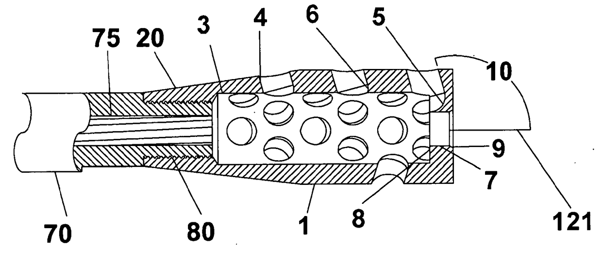
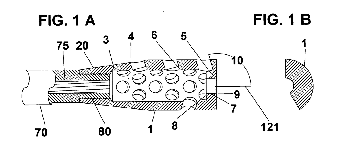
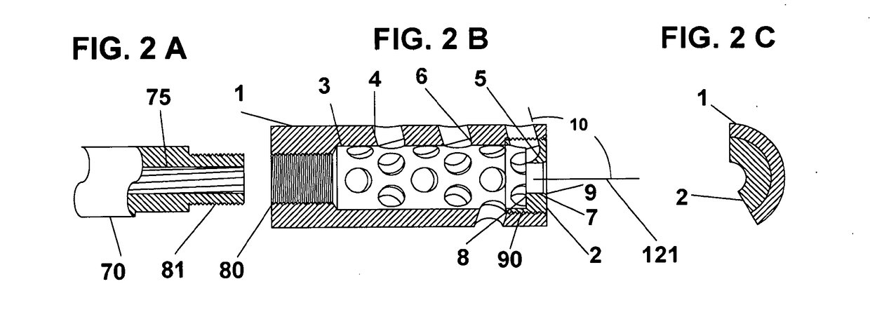
[0042]FIG. 1A illustrates one embodiment of muzzle brake 1 constructed in accordance with various features of the present general inventive concept. In the illustration of FIG. 1A, a muzzle end of a firearm barrel 70 is illustrated. The firearm barrel 70 defines a substantially cylindrical bore 75 defining rifling therein and opens outwardly to a muzzle end 81 (see FIG. 2A) thereof. In the various figures, the illustrated muzzle end 81 defines a plurality of external threads of the type commonly used to attach any of various firearm accessories thereto. With initial reference to FIG. 1A, in one embodiment, a muzzle brake 1 is provided having a generally internally and externally cylindrical shape and having a first end defining an internally threaded 80 opening adapted to mate with and engage the external threads of the externally threaded muzzle end 81 of the firearm barrel 70 in order to secure the muzzle brake 1 to the firearm barrel 70. The internally threaded 80 first end of th...


PUM


Abstract

A muzzle brake for high power rifles, hand guns, machine guns, and artillery, exhibiting barrel stabilization and recoil reduction, by capturing gasses against an orifice end plate and redirecting these gases both out of the muzzle brake, and into the muzzle brake to fill the partial vacuum left by the exiting high pressure gases, by way of Major truncated socket forms, and to a lesser extent, with the use of Minor truncated socket forms, and their associated vent ports in an asymmetrical pattern that balances barrel lift, and recoil against the expected and recovered gases.

Description

CROSS-REFERENCE TO RELATED APPLICATIONS[0001]This application claims priority to U.S. Provisional Patent Application Ser. No. 62 / 459,338, filed on Feb. 15, 2017. This application is also a continuation-in-part of U.S. patent application Ser. No. 15 / 855,333, filed on Dec. 27, 2017, which is a continuation of U.S. patent application Ser. No. 15 / 066,988, filed on Mar. 10, 2016. Each of the aforementioned applications is hereby incorporated herein in its entirety by reference.STATEMENT REGARDING FEDERALLY SPONSORED RESEARCH OR DEVELOPMENT[0002]Not ApplicableFIELD OF THE INVENTION[0003]The present general inventive concept pertains to firearms, and more particularly, to muzzle brakes of the type designed to control firearm recoil, barrel lift, and lateral deflection of hand guns, high power rifles, mounted guns, and other firearms during and after discharge of a projectile therefrom by capturing high pressure gas generated during discharge of the projectile and using the high pressure ga...

Claims


Application Information

Patent Timeline
Patent Type & Authority Applications(United States)
IPC IPC(8): F41A21/36F41C27/22
CPCF41A21/36F41C27/22
Inventor GRIFFITTS, JAMES NORMAN
Owner GRIFFITTS JAMES NORMAN
Learn More