
Thermal chemical vapor deposition coating

a chemical vapor deposition and coating technology, applied in chemical vapor deposition coating, coating, metallic material coating process, etc., can solve the problems of limited flow-through process, high cost and waste, and single-layer process of atomic layer deposition that has substantial economic challenges

Active Publication Date: 2018-09-13
SILCOTEK CORP
View PDF1 Cites 4 Cited by
  • Summary
  • Abstract
  • Description
  • Claims
  • Application Information

AI Technical Summary

Benefits of technology

The patent text describes a process for coating articles with a thermal chemical vapor deposition coating that has multiple layers and is positioned on regions of the article that are unable to be concurrently coated through line-of-sight techniques. The coating has a low concentration of particulate, with a per (100 square micrometers) measurement of fewer than 6 particles having a dimension greater than 0.5 micrometers. The process includes positioning the article in an enclosed vessel and introducing a silicon-containing precursor to the vessel in two stages to produce the coating. The resulting coating has improved properties and can be used in various applications.

Problems solved by technology

However, such flow-through processes are limited to line-of-sight techniques that coat surfaces within a direct line or substantially close to the direct line.
Such flow-through processes are expensive and wasteful by having an over-abundance of the gas precursor that does not deposit on such surfaces.
However, atomic layer deposition is a single layer process that has substantial economic challenges due to the prolonged processing conditions required to achieve coating.
However, many of the prior techniques produce gas phase nucleation based upon particle-particle collisions during the reaction process.
Certain industries are extremely sensitive.
They require reproducibility that has previously been considered to be beyond the functional possibility for thermal chemical vapor deposition and were only capable of being satisfied through wasteful flow-through techniques.
Although the amount of dust may be at levels below in which silicon dust can settle on the surface, compromise the integrity of the silicon layer formed on the metal surface, and / or create a physical barrier between successive layers of silicon, such levels can be too high for certain industries.

Method used


Image

  • Thermal chemical vapor deposition coating
  • Thermal chemical vapor deposition coating
  • Thermal chemical vapor deposition coating

Examples


examples

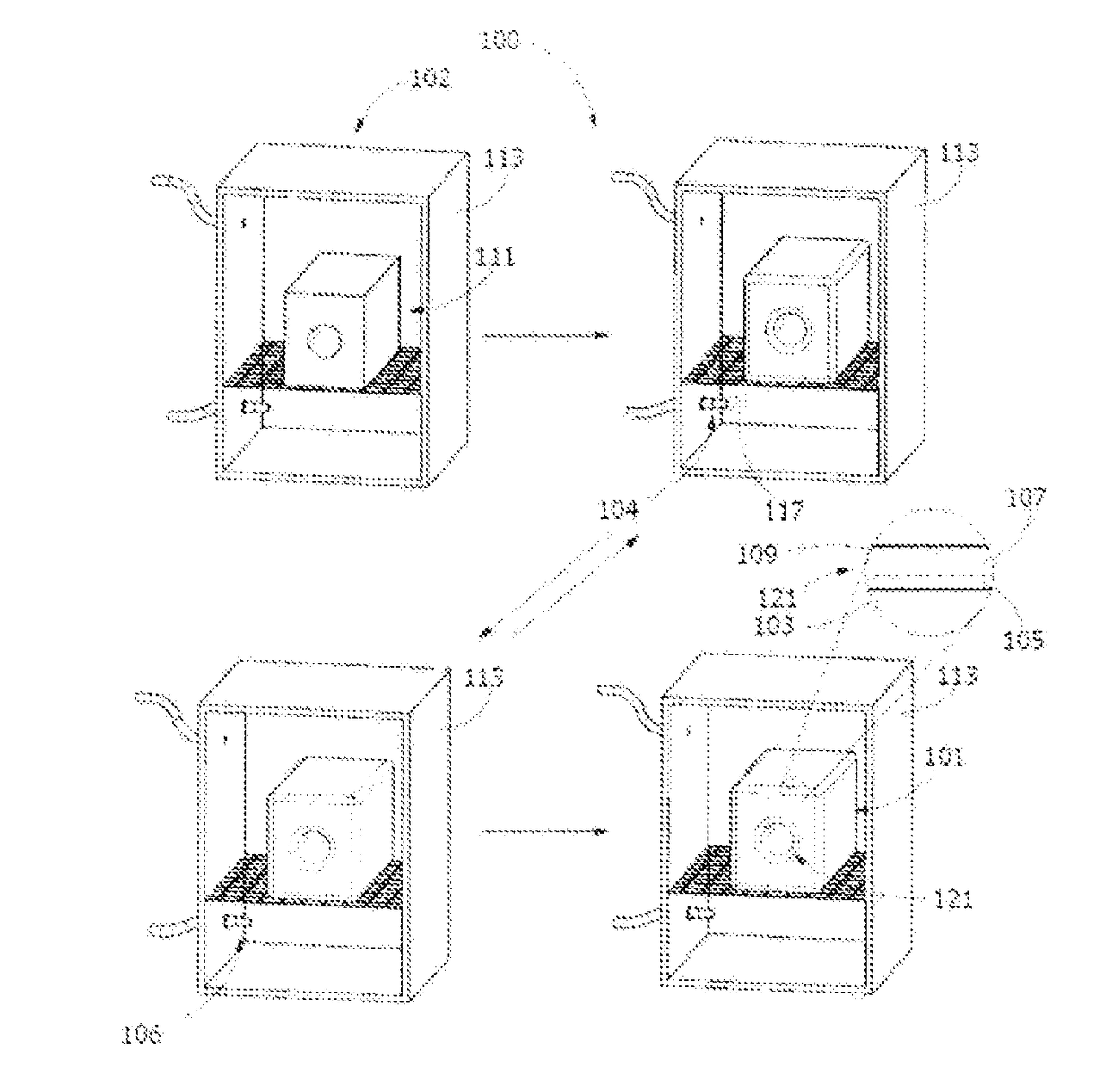
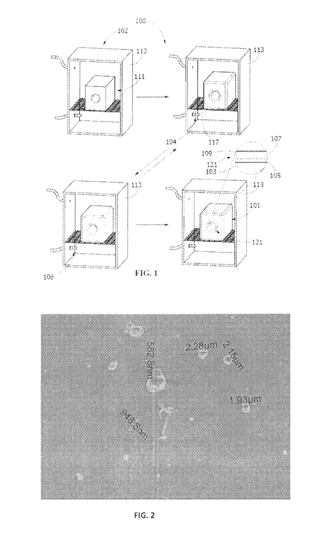
[0063]In a first experiment, a stainless steel coupon was coated at 390° C. at a pressure of 7.75 psia for four 30-minute cycles. The coated stainless steel coupon resulted in a coating substantially free of silicon dust, but with dust at a minute concentration of, per 100 square micrometers, greater than 6 particles having a dimension of greater than 0.5 micrometers.

[0064]In a second experiment, a stainless steel coupon was coated at 410° C. at a pressure of 3.87 psia for four 45-minute cycles. The coated stainless steel coupon resulted in a coating substantially free of silicon dust, but with dust at a minute concentration of, per 100 square micrometers, greater than 6 particles having a dimension of greater than 0.5 micrometers.

[0065]In a third experiment, a stainless steel coupon was coated at 410° C. at a pressure of 2.32 psia for four 45-minute cycles. The coated stainless steel coupon resulted in a coating substantially free of silicon dust, but with dust at a minute concentr...


PUM

PropertyMeasurementUnit
thicknessaaaaaaaaaa
thicknessaaaaaaaaaa
surface reaction rateaaaaaaaaaa

Abstract

Thermal chemical vapor deposition coated articles and thermal chemical vapor deposition processes are disclosed. The thermal chemical vapor deposition coated article includes a substrate and a coating on the substrate, the coating having multiple layers and being positioned on regions of the thermal chemical vapor deposition coated article that are unable to be concurrently coated through line-of-sight techniques. The coating has a concentration of particulate from gas phase nucleation, per 100 square micrometers, of fewer than 6 particles having a dimension of greater than 0.5 micrometers. The thermal chemical vapor deposition process includes introducing a multiple aliquot of a silicon-containing precursor to the enclosed vessel with intermediate gaseous soaking to produce the coated article.

Description

PRIORITY[0001]The present application is a non-provisional patent application claiming priority and benefit of U.S. Provisional Patent Application No. 62 / 212,868, filed on Sep. 1, 2015 and directed to “BATCH THERMAL CVD SILICON PARTICULATE REDUCTION AND / OR ELIMINATION” which is incorporated by reference in its entirety.FIELD OF THE INVENTION[0002]The present invention is directed to thermal chemical vapor deposition coated articles and thermal chemical vapor deposition processes. More particularly, the present invention is directed to multilayer coatings.BACKGROUND OF THE INVENTION[0003]Silicon has been applied to various surfaces through thermal chemical vapor deposition. Silicon has been applied through static processes involving pump and purge cycling of a reaction vessel, with periods of a gaseous soak within the reaction vessel. Alternatively, silicon has been applied in flow-through systems that involve constant flow of a gas through a reaction chamber, which do not include th...

Claims


Application Information

Patent Timeline
Patent Type & Authority Applications(United States)
IPC IPC(8): C23C16/455C23C16/24
CPCC23C16/45523C23C16/24C23C16/045
Inventor VEZZA, THOMAS F.MATTZELA, JAMES B.BARONE, GARY A.GROVE, WILLIAM DAVIDSILVIS, PAUL H.
Owner SILCOTEK CORP
Learn More