Multi degree of freedom flutter damper

a technology of flutter damper and multi-degree freedom, which is applied in the direction of efficient propulsion technology, machines/engines, liquid fuel engines, etc., can solve the problems of aeromechanical instability and detrimental to the life of the fan blade, and achieve the effect of reducing the risk of flutter

Active Publication Date: 2018-09-13
RTX CORP
View PDF4 Cites 13 Cited by
  • Summary
  • Abstract
  • Description
  • Claims
  • Application Information

AI Technical Summary

Benefits of technology

[0009]In addition to one or more of the features described above, or as an alternative, further embodiments may include a cover sheet disposed on the acoustic perforated only in areas between the acoustic liner and the plurality of modular chambers.
[0010]In addition to one or more of the features described above, or as an alternative, further embodiments may include that the chamber segments are box or rectangular shaped.
[0011]In addition to one or more of the features described above or as an alternative, further embodiments may include that the chamber segments not box shape (e.g., may be elliptically shaped).
[0012]In addition to one or more of the features described above or as an alternative, each of the box or elliptical shaped chambers may have a different external dimension while maintaining a desired volume.
[0013]In addition to one or more of the features described above or as an alternative, the modular chambers are a metallic material, including aluminum, or a plastic or a composite, or a hybrid metallic and non-metallic material.
[0014]Further disclosed is a gas turbine engine system, including a nacelle, and a flutter damper disposed within the nacelle. The flutter damper may include one or more of the above disclosed features.

Problems solved by technology

Fan flutter is an aeromechanical instability detrimental to the life of a fan blade.

Method used


Image

  • Multi degree of freedom flutter damper
  • Multi degree of freedom flutter damper
  • Multi degree of freedom flutter damper

Examples


Embodiment Construction

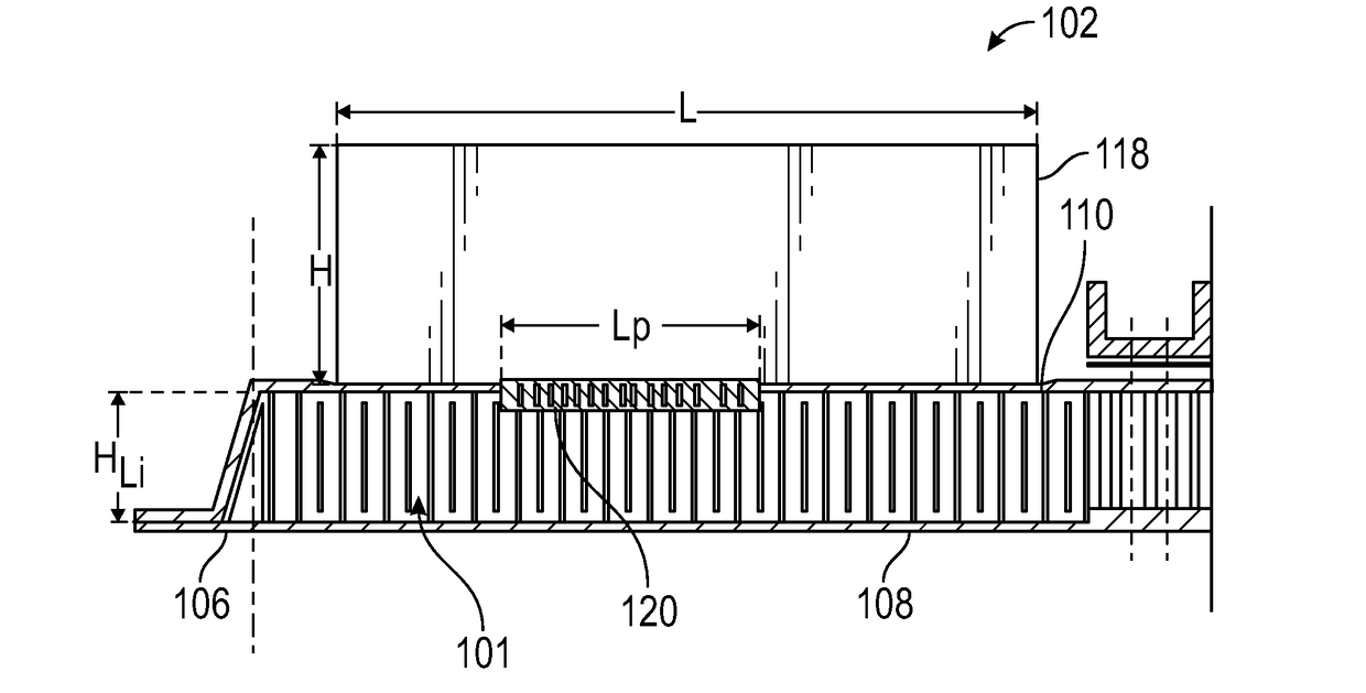
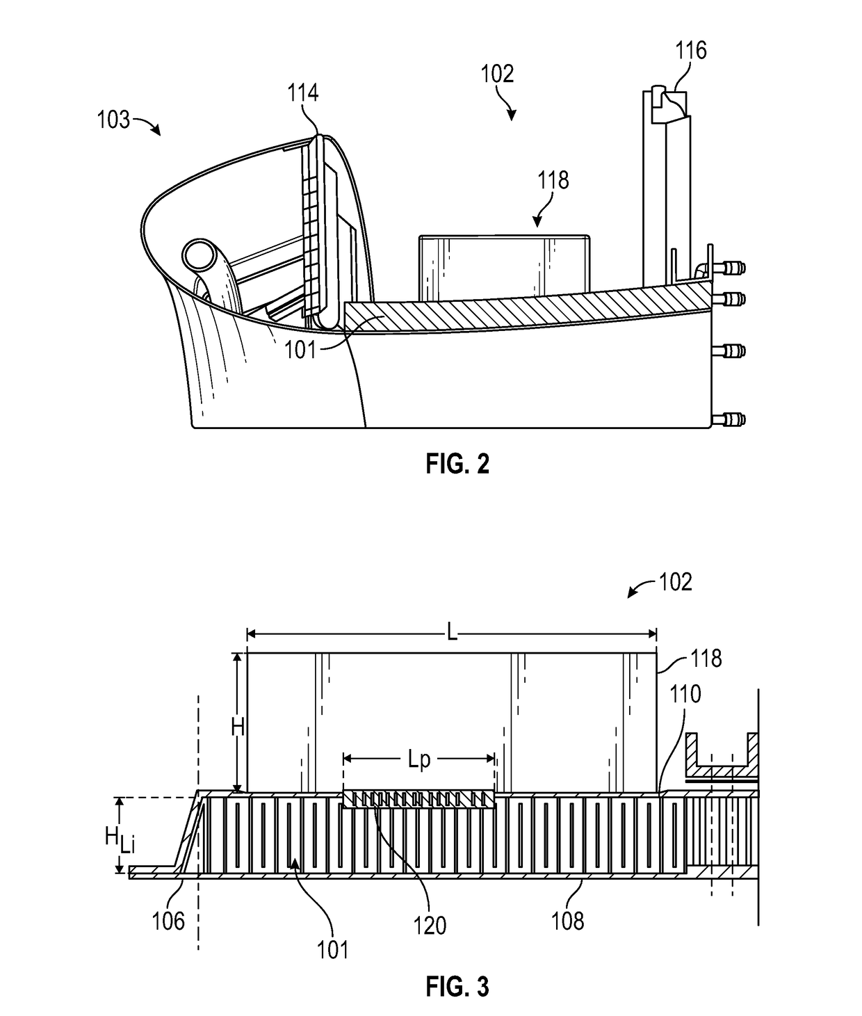
[0026]A detailed description of one or more embodiments of the disclosed apparatus and method are presented herein by way of exemplification and not limitation with reference to the Figures.

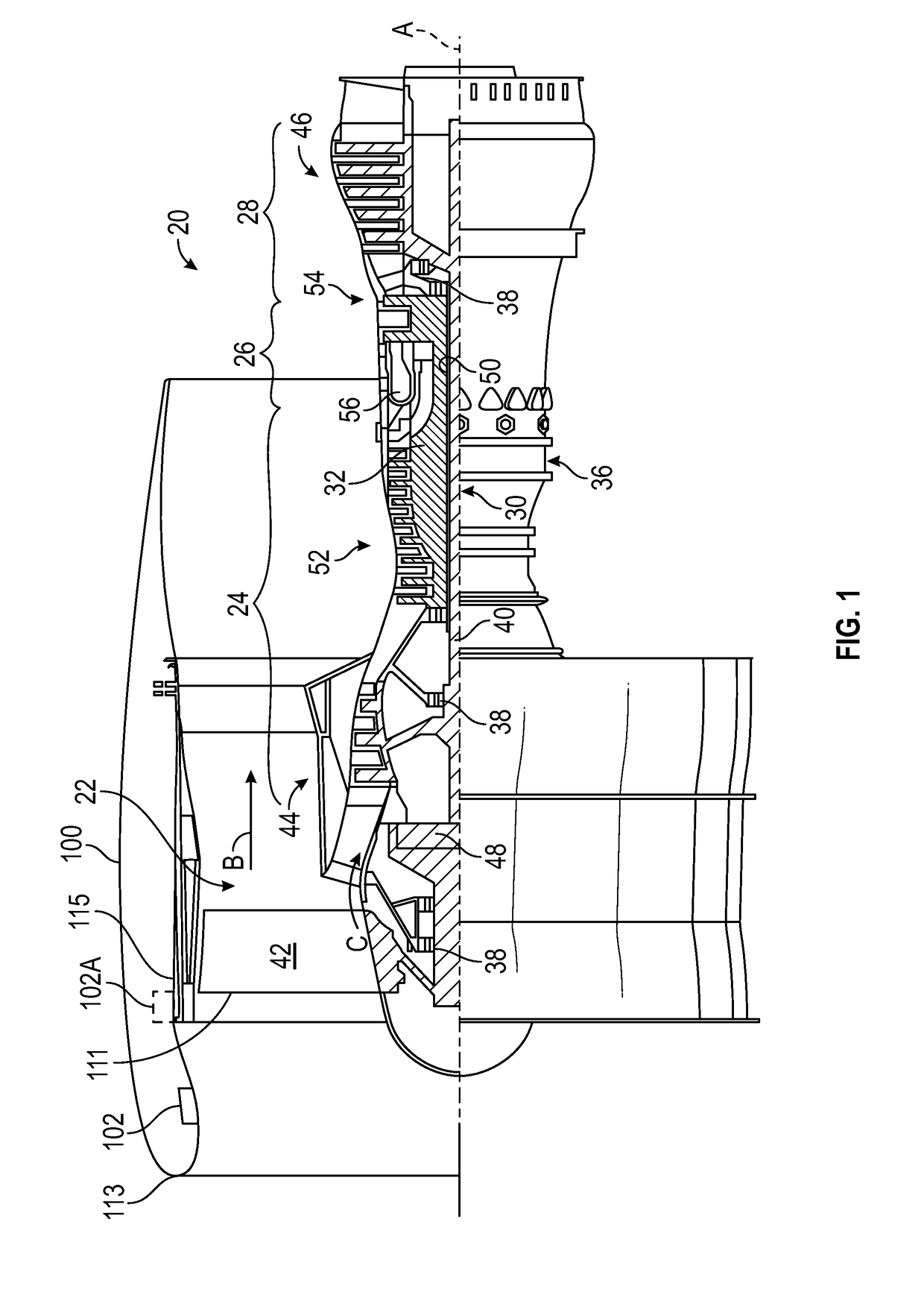
[0027]FIG. 1 schematically illustrates a gas turbine engine 20. The gas turbine engine 20 is disclosed herein as a two-spool turbofan that generally incorporates a fan section 22, a compressor section 24, a combustor section 26 and a turbine section 28. Alternative engines might include an augmentor section (not shown) among other systems or features. The fan section 22 drives air along a bypass flow path B in a bypass duct, while the compressor section 24 drives air along a core flow path C for compression and communication into the combustor section 26 then expansion through the turbine section 28. Although depicted as a two-spool turbofan gas turbine engine in the disclosed non-limiting embodiment, it should be understood that the concepts described herein are not limited to use with two-spool...


PUM


Abstract

Disclosed is a flutter damper, including an acoustic liner in fluid communication with a fluid flow, the acoustic liner being configured for peak acoustical energy absorption at a frequency range that is greater than a frequency range associated with fan flutter, and a plurality of modular chambers, each of the plurality of modular chambers being configured for peak acoustical energy absorption at a frequency range that is associated with one or more fan flutter modes, and the plurality of modular chambers being disposed radially outside of the acoustic liner, and the plurality of modular chambers including a circumferential gap between proximate circumferential ends of at least one adjacent pair of modular chambers, wherein, the plurality of modular chambers each include a plurality of circumferentially aligned and connected chamber segments.

Description

BACKGROUND[0001]Exemplary embodiments pertain to flutter dampers in gas turbine propulsion systems and, more particularly, to flutter dampers in nacelle inlet structures.[0002]Geared turbofan architectures, allow for high bypass ratio turbofans, enabling the use of low pressure ratio fans, which may be more susceptible to fan flutter than high pressure ratio fans. Fan flutter is an aeromechanical instability detrimental to the life of a fan blade.[0003]Accordingly, there is a need for a flutter damper which, by absorbing the acoustic energy associated with the flutter structural mode, may prevent the fan from fluttering, and which may be integrated into the reduced available space in an optimized propulsion system.BRIEF DESCRIPTION[0004]Disclosed is a flutter damper, including an acoustic liner in fluid communication with a fluid flow, the acoustic liner being configured for peak acoustical energy absorption at a frequency range that is greater than a frequency range associated with...

Claims


Application Information

Patent Timeline
Patent Type & Authority Applications(United States)
IPC IPC(8): F04D29/66F04D29/52F02K3/06
CPCF04D29/664F05D2220/32F02K3/06F04D29/526F02C7/045F05D2260/963Y02T50/60
Inventor LEVASSEUR, GLENNSINGH, RYAN A.
Owner RTX CORP
Why Eureka
Try Eureka