
Wide angle variable neutral density filter

a neutral density filter and wide angle technology, applied in the field of wide angle variable neutral density filter, can solve the problems of limiting the usefulness of practice, limiting the transmission uniformity of ideal crossed polarizers, and limiting the use of contrast or color uniformity, etc., to reduce the angle resolution requirement, reduce the effect of transmitting brightness and color non-uniformity, and eliminating ar coatings

Active Publication Date: 2018-09-13
META PLATFORMS TECH LLC
View PDF0 Cites 11 Cited by
  • Summary
  • Abstract
  • Description
  • Claims
  • Application Information

AI Technical Summary

Benefits of technology

This patent describes a new design for an optical system that reduces non-uniformity and improves image quality. By adding a third polarizer and adjusting the angles between the different polarizers, the system can achieve higher quality images over a wider range of settings. The use of optical grease and lamination techniques eliminates the need for additional coatings and ensures flatness of the polarizers. Overall, this design provides improved image quality and reduced non-uniformity in optical systems.

Problems solved by technology

The issue is that VND filters in the industry tend to introduce spatial / angular artifacts that limit their usefulness in practice.
Because of these artifacts, a contrast or color non-uniformity may preclude wide-angle shots and / or high density when the VND filter is placed in front of the camera lens.
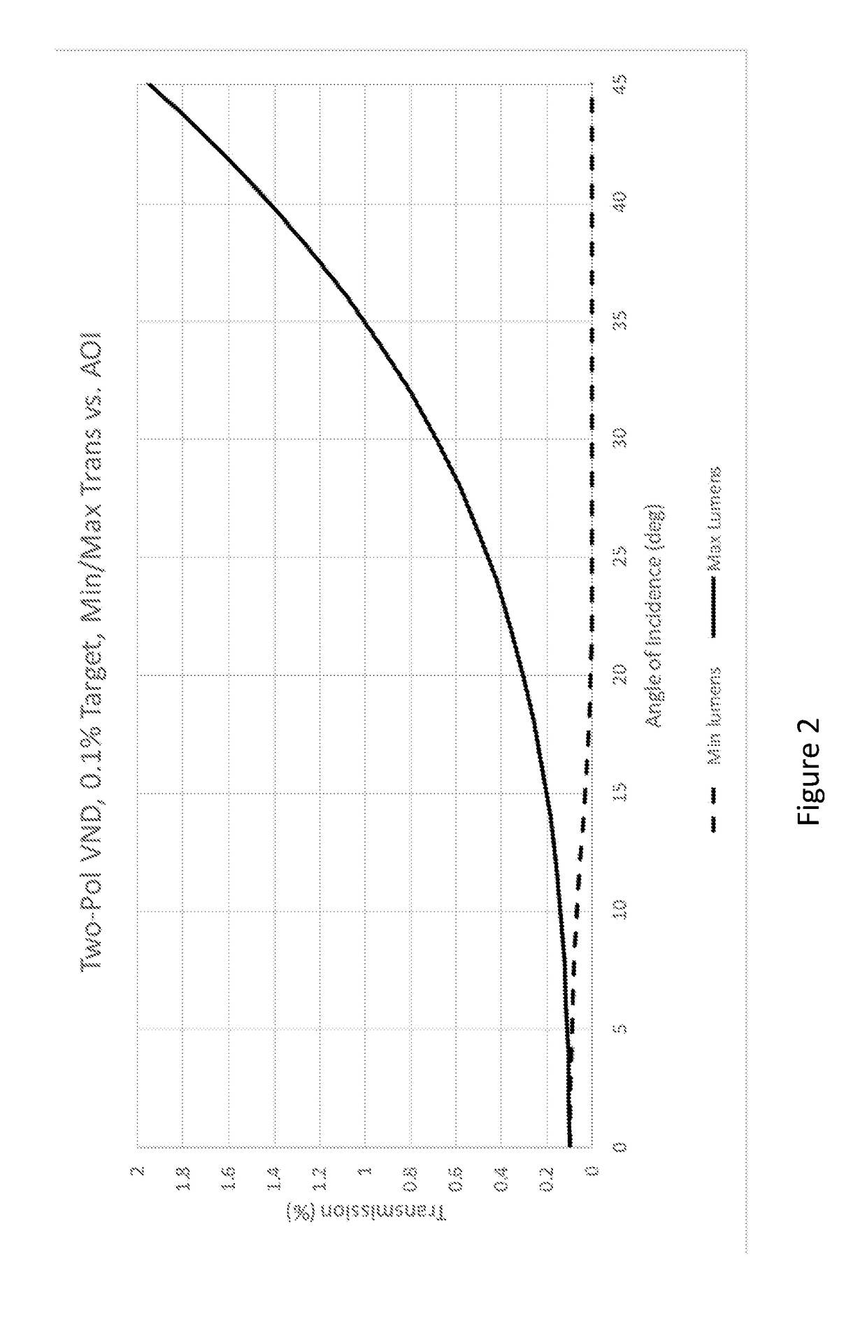
Transmission non-uniformity of ideal crossed polarizers is the result of rotation of the absorption axes due entirely to geometry.
In the context of VND filters, the most problematic cases occur near crossed polarizers, corresponding to selection of higher densities.
TAC can also introduce additional haze that contributes to veiling glare.
However, the ability to maintain uniform transmission and color over a 45° half-cone angle, and over the full range of density tuning, is extremely challenging for LC devices.
This may force them into positions in the optical train where light is more collimated, a situation that may be undesirable.
Moreover, there can be disadvantages to an electro-optic device (e.g. for unmanned aerial vehicles, UAVs, or drones), where the need for constant application of a DC-balanced drive voltage results in an undesirable consumption of power.

Method used


Image

  • Wide angle variable neutral density filter
  • Wide angle variable neutral density filter
  • Wide angle variable neutral density filter

Examples


Embodiment Construction

[0029]While the embodiments disclosed herein are susceptible to various modifications and alternative forms, specific embodiments thereof have been shown by way of example in the drawings and are herein described in detail. It should be understood, however, that it is not intended to limit the invention to the particular form disclosed, but rather, the invention is to cover all modifications, equivalents, and alternatives of embodiments of the invention as defined by the claims. The disclosure is described with reference to the drawings, wherein like reference numbers denote substantially similar elements.

[0030]Today, photographers and videographers can either select between a set of fixed neutral density filters, VND filters with high-contrast achromatic cross artifacts, or lower-contrast chromatic cross artifacts. There is thus a long-standing need, particularly in photography and video capture, for a variable neutral density filter that is truly neutral and maintains high uniform...


PUM


Abstract

A three (or more) polarizer arrangement is used to demonstrate a wide-angle variable-neutral-density (VND) filter that has both contrast uniformity and color uniformity. According to one embodiment, the outer polarizers effectively counter-rotate with respect to a fixed center polarizer as a means of compensating for transmission non-uniformity associated with geometrical polarization distortions experienced by off-normal rays. In particular, the achromatic compensation arrangement enables angle uniformity relative to normal-incidence transmission when the number of stops of attenuation grows large (e.g. 10-stops, or OD3). The filters are useful for cameras or instrumentation allowing mechanical or electromechanical tuning.

Description

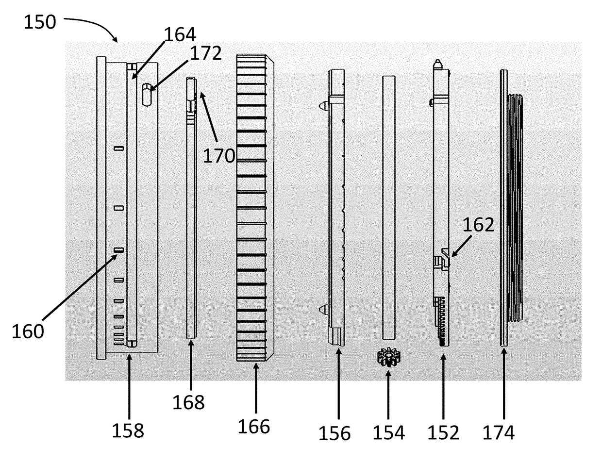
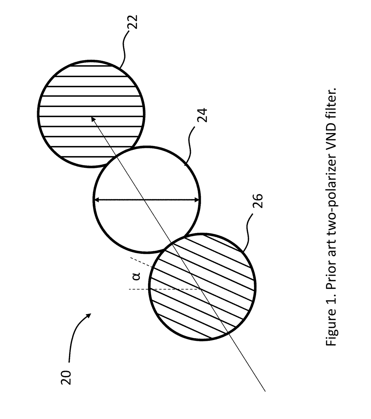
CROSS-REFERENCE TO RELATED APPLICATIONS[0001]This application claims the benefit of U.S. Provisional Application No. 62 / 468,803, filed March 8, the content of which is incorporated herein by reference in its entirety.BACKGROUND[0002]There is a long-standing need, particularly for video and still cameras, to have a filter attachment with a large range in tunable attenuation. For example, a variable neutral density (VND) filter can enable selection of exposure time independent of scene luminance, giving photographers a valued degree of freedom. VND filters use polarization as a means of varying transmission. When polarizer absorption axes are parallel, the transmission is maximum. As one polarizer is rotated with respect to the other (see FIG. 1) the transmission drops, with theoretically zero transmission when the absorption axes are crossed. The issue is that VND filters in the industry tend to introduce spatial / angular artifacts that limit their usefulness in practice. Because of t...

Claims


Application Information

Patent Timeline
IPC IPC(8): G02B5/20G02B5/30H04N5/225
CPCG02B5/205G02B5/3041H04N5/2254G02B27/281H04N23/55
Inventor SHARP, GARY D.MCGETTIGAN, ANTHONY D.
Owner META PLATFORMS TECH LLC
Learn More