Elevator synchronous door knife

a technology of synchronous doors and elevators, applied in the field of elevator technology, can solve the problems of time being too long or crash, and achieve the effect of simplifying the mechanical structure and facilitating debugging

Active Publication Date: 2018-09-20
OTIS ELEVATOR CO
View PDF0 Cites 13 Cited by
  • Summary
  • Abstract
  • Description
  • Claims
  • Application Information

AI Technical Summary

Benefits of technology

[0005]The present invention mainly solves the problems in the prior art that a general synchronous door knife has an unreasonable structure, is not easy to debug, takes a long time to open the door, and is easy to get stuck, and provides an elevator synchronous door knife which has a simple structure, is easy to debug and is not easy to crash.
[0006]The aforementioned technical problem of the present invention is mainly solved through the following technical solution: an elevator synchronous door knife, including a track frame disposed on a door motor back plate and a bottom plate disposed on a hanging plate, wherein the back of the bottom plate is hinged with a stop arm, a transmission arm linked with a door motor driving mechanism and a lock plate buckled with a lock hook disposed on a lift car, a front end of the stop arm is provided with a guide wheel fitting in with the track frame, upper and lower portions of the front of the bottom plate are respectively rotationally connected with an upper rotating arm and a lower rotating arm, the upper rotating arm is linked with the transmission arm through a draw bar, one end of the upper rotating arm and the lower rotating arm is movably connected with a first blade, the other end of the upper rotating arm and the lower rotating arm is hinged with a movable plate, to form a four-bar linkage, upper and lower portions of the movable plate are respectively movably connected with an upper unlock rotating arm and a lower unlock rotating arm, the upper unlock rotating arm and the lower unlock rotating arm are movably connected with a second blade, and the upper unlock rotating arm further abuts against the lock plate to drive the lock plate to be unlocked or locked up. The present invention integrates a door closing blade and an unlock blade in a general synchronous door knife structure onto one blade, and simplifies a mechanical structure, thus reducing the requirement for precision of adjusting matching positions of a door knife and a landing door ball, to make debugging much easier. In addition, the problem that the time is too long or crash occurs when mechanical reopening of a landing door is blocked at the end of door closing is also solved. In the present invention, the unlock blade is removed, and the second blade is connected with the unlock rotating arm, and simultaneously plays a role of driving the unlock rotating arm to rotate.
[0007]As one preferred solution, in a horizontal direction, a sequence of positions from the first blade to the second blade is kept consistent with a door opening direction. The door opening direction is a direction in which the door plate moves when the door of the elevator is opened, and an advantage of keeping a sequence of positions from the first blade to the second blade consistent with a door opening direction in a horizontal direction is as follows: as the second blade has a function of an unlock blade, normal opening and closing of the door are not affected no matter how the landing door ball is offset-mounted. Specifically, for example, when the landing door ball is offset-mounted close to the unlock blade, the car door lock is unlocked in advance during clamping of the door knife, then the car door is opened first, the landing door is motionless, and finally the door knife is completely clamped so as to be opened together with the landing door; when the landing door ball is offset-mounted away from the unlock blade, the landing door lock is unlocked in advance during clamping of the door knife, then the landing door is opened first, the car door is motionless, and finally the door knife is completely clamped so as to unlock the car door lock to be opened together with the landing door.
[0012]As one preferred solution, a lower side of a front end of the lock plate has an inwardly concave arc edge used to lift up the lock plate, the upper unlock rotating arm abuts against the inwardly concave arc edge, a rear end of the lock plate extends to form a shifting portion, the front end of the lock plate is further provided with a lock tongue, the lock tongue is buckled with the lock hook on the lift car, and a second reset spring is further connected between an upper portion of the front end of the lock plate and the bottom plate. The second reset spring is a pressure spring, the second reset spring is vertically disposed above the lock plate, one end is connected to the upper portion of the lock plate, and one end is connected onto the bottom plate, to make the lock plate keep a pressed state.
[0015]As one preferred solution, the back of the stop arm is provided with a third limit shaft, a corresponding position of the bottom plate is provided with a second limit slot, the third limit shaft passes through the second limit slot to expose to the front of the bottom plate, and a fourth reset spring is connected between the third limit shaft and the bottom plate. The fourth reset spring is uprightly or obliquely disposed, an upper end of the fourth reset spring is connected onto the third limit shaft, a lower end is connected onto the bottom plate, and the fourth reset spring keeps a pressed state of the stop arm. The second limit slot limits a range of rotation of the limit shaft.
[0016]Therefore, the present invention has the following advantages: 1. a mechanical structure is simplified, only a first blade and a second blade are disposed, and functions of a door closing blade and an unlock blade are integrated onto the second blade; 2. as the second blade also has the function of the unlock blade, normal opening and closing of the door are not affected no matter how the landing door ball is offset-mounted or keeps far away, which reduces the requirement for precision of adjusting matching positions of a door knife and a landing door ball, to make debugging much easier; and 3. a problem that the door motor fails to work when the landing door ball is offset-mounted away from the unlock blade and a problem that the time is too long or crash occurs when mechanical reopening of the landing door is blocked at the end of door closing are solved at the same time.

Problems solved by technology

In addition, the problem that the time is too long or crash occurs when mechanical reopening of a landing door is blocked at the end of door closing is also solved.

Method used


Image

  • Elevator synchronous door knife
  • Elevator synchronous door knife
  • Elevator synchronous door knife

Examples


Embodiment Construction

[0023]The technical solution of the present invention is further described below through embodiments and in combination with the accompanying drawings.

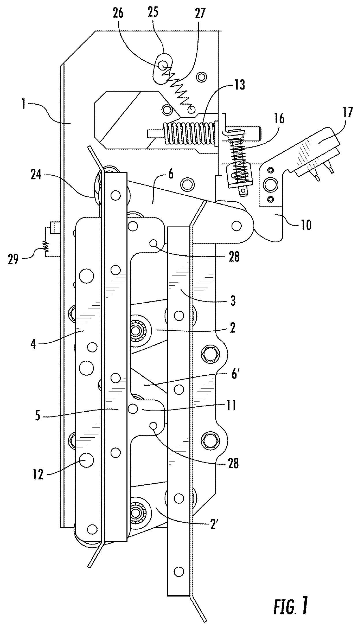
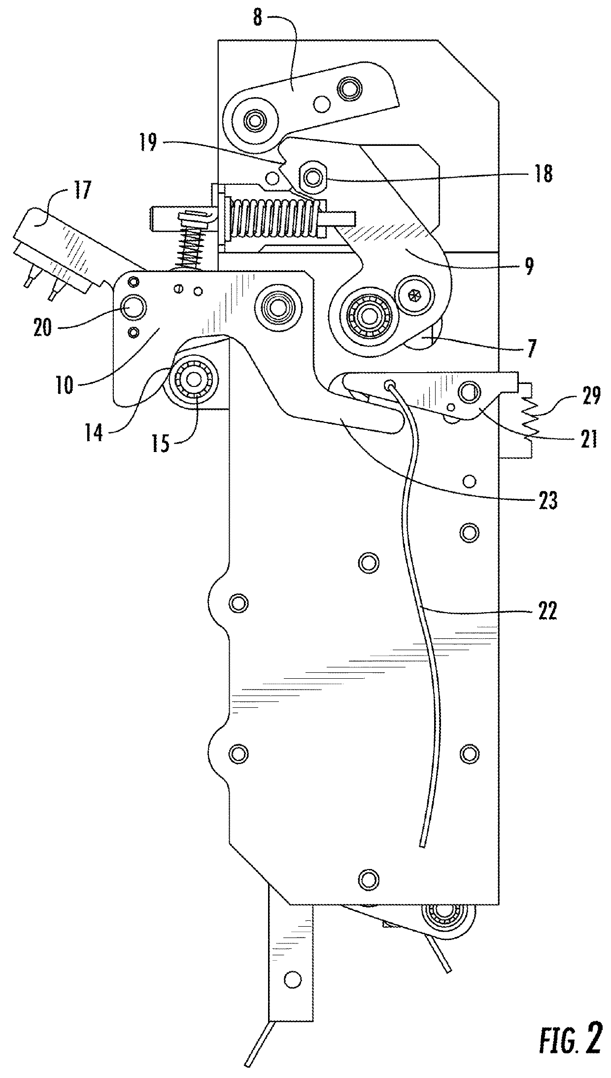
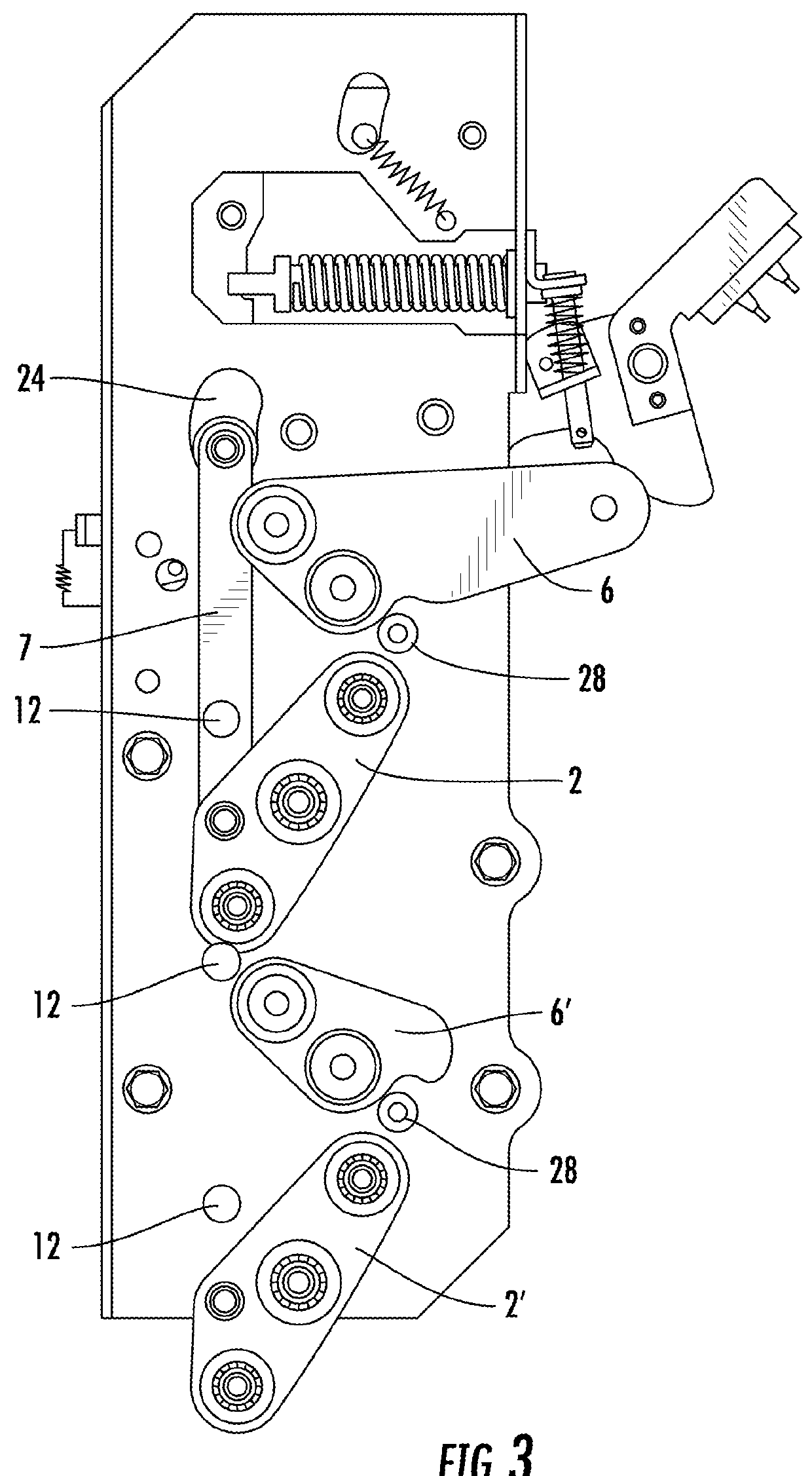
[0024]This embodiment provides an elevator synchronous door knife, which, as shown in FIG. 1, includes a bottom plate 1 disposed on a hanging plate, wherein upper and lower portions of the front of the bottom plate are respectively rotationally connected with an upper rotating arm 2 and a lower rotating arm 2′, right ends of the two rotating arms are rotationally connected with a first blade 3, and left ends of the two rotating arms are rotationally connected with a movable plate 4. The movable plate is rotationally connected with an upper unlock rotating arm 6 and a lower unlock rotating arm 6′, and the upper unlock rotating arm and the lower unlock rotating arm are rotationally connected with a second blade 5. As shown in FIG. 2, the back of the bottom is rotationally connected with a stop arm 8, a transmission arm 9 linked with a d...


PUM


Abstract

A synchronous door knife includes a track frame and a bottom plate, the back of the bottom plate is hinged with a stop arm, a transmission arm and a lock plate, a front end of the stop arm is provided with a guide wheel, upper and lower portions of the front of the bottom plate are respectively hinged with rotating arms, the upper rotating arm is linked with the transmission arm through a draw bar, one end of the rotating arms is hinged with a first blade, the other end is hinged with a movable plate, the movable plate is hinged with unlock rotating arms, one end of the unlock rotating arms is hinged with a second blade, and the other end abuts against the lock plate.

Description

TECHNICAL FIELD[0001]The present invention relates to the field of an elevator technology, and in particular, to an elevator synchronous door knife which has a simple structure, is easy to debug and is not easy to crash.RELATED ART[0002]The door knife type of vertical elevators is divided into two types, i.e., a synchronous type and an asynchronous type, good appearance effects brought about by synchronous door knives due to synchronization of hall car doors are favored by users, but the synchronous door knives put forward higher requirements for mounting and debugging. Such door knives require electrical matching when implementing a function of blocking mechanical reopening of a landing door, and when the function is implemented, crash may occur or at least poor experience will be brought about to the users.[0003]The synchronous door knife of the existing integrated car door usually has three blades, which can be divided into a door opening blade, a door closing blade and an unlock...

Claims


Application Information

Patent Timeline
Patent Type & Authority Applications(United States)
IPC IPC(8): B66B13/12
CPCB66B13/12
Inventor ZHANG, XIAOBOCAI, QINGXIDONG, XIAOXIAOCHEN, CHONG
Owner OTIS ELEVATOR CO
Why Eureka
Try Eureka