Rotary machine single-suction intake device

a single-suction, intake device technology, applied in machines/engines, liquid fuel engines, combustion air/fuel air treatment, etc., can solve problems such as performance variations of rotary machines, and achieve the effect of simple configuration and reduction of asymmetry

Inactive Publication Date: 2018-09-20
MITSUBISHI HEAVY IND LTD +1
View PDF3 Cites 2 Cited by
  • Summary
  • Abstract
  • Description
  • Claims
  • Application Information

AI Technical Summary

Benefits of technology

[0020]According to the rotary machine single-suction intake device of the present invention, it is possible to reduce asymmetry between the flow speed of the fluid flowing in the forward direction relative to the rotational direction of the rotating shaft of the compressor and the flow speed of the fluid flowing in the opposite direction relative thereto using a simple configuration.

Problems solved by technology

Since the flow distortion generates a peripheral direction distribution in the inlet of the rotary machine, there is a problem that variation in performance of the rotary machine occurs in the peripheral direction of the rotating shaft.

Method used


Image

  • Rotary machine single-suction intake device
  • Rotary machine single-suction intake device
  • Rotary machine single-suction intake device

Examples


example 1

[0040]A rotary machine single-suction intake device according to Example 1 of the present invention will be described with reference to FIGS. 1 to 4B.

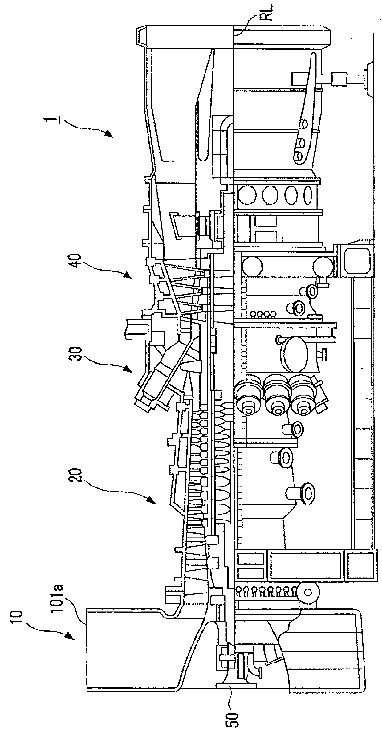
[0041]As shown in FIG. 1, the rotary machine single-suction intake device according to the present Example is a single-suction intake duct 10 which is disposed on an upstream side of a gas turbine 1 and suctions air (fluid) in a direction approximately orthogonal to a rotational axis RL. In addition, a reference numeral 20 in FIG. 1 indicates a compressor (axial compressor), a reference numeral 30 indicates a combustor, a reference numeral 40 indicates a turbine, and a reference numeral 50 indicates a rotating shaft.

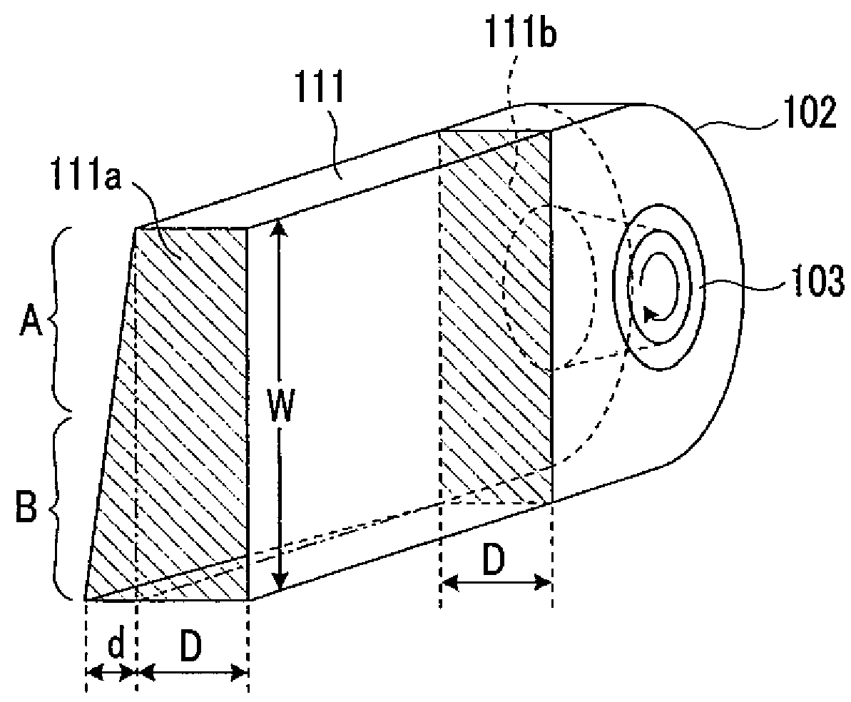
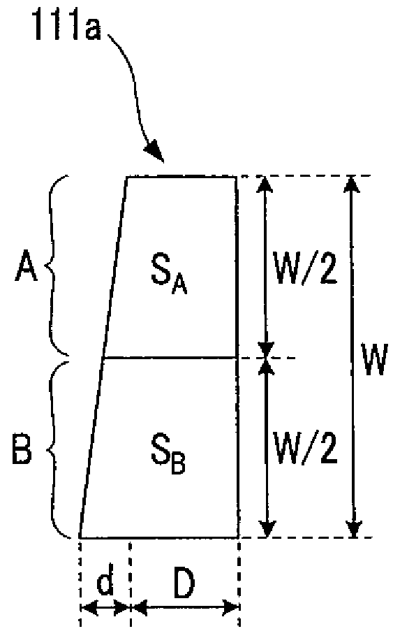
[0042]The rotary machine single-suction intake device according to the present Example adopts an upstream duct (upstream side casing) 111 shown in FIG. 2 instead of the above-described upstream duct 101 in the related art shown in FIG. 10. Other configurations are approximately similar to the configurations of the related a...

example 2

[0055]A rotary machine single-suction intake device according to Example 2 of the present invention will be described with reference to FIGS. 5A to 5C.

[0056]The rotary machine single-suction intake device according to the present Example adopts an intake duct body section (downstream side casing) 112 shown in FIGS. 5A to 5C instead of the above-described intake duct body section 102 of the related art shown in FIG. 10. Other configurations are approximately similar to the configurations of the related art, and hereinafter, the configurations different from those of the intake duct shown in FIG. 10 are mainly described, and overlapping descriptions are omitted.

[0057]As shown in FIGS. 5A to 5C, in the intake duct body section 112 of the present Example, a shape of a compressor-side channel 112a is different from that of the intake duct body section 102 of the related art. Specifically, while an outer diameter side wall surface (hereinafter, referred to as a channel outer diameter-side...

example 3

[0068]A rotary machine single-suction intake device according to Example 3 of the present invention will be described with reference to FIGS. 6A to 9C.

[0069]The rotary machine single-suction intake device according to the present Example adopts an upstream duct (upstream side casing) 121 shown in FIGS. 6A and 6B instead of the above-described upstream duct (upstream side casing) 101 of the related art shown in FIG. 10. Other configurations are approximately similar to the configurations of the related art, and hereinafter, the configurations different from those of the intake duct shown in FIG. 10 are mainly described, and overlapping descriptions are omitted.

[0070]As shown in FIGS. 6A and 6B, in the upstream duct 121 of the present Example, a shape of the upstream duct 121 on a suction port 121a side is different from that of the upstream duct 101 of the related art. Specifically, the shape of the upstream duct 121 on the forward direction side A is different from that of the relat...


PUM


Abstract

The present invention provides a rotary machine intake casing which, by using a simple configuration, makes it possible to reduce asymmetry between the flow speed of air flowing in a forward direction relative to the direction of rotation of a rotating shaft of a compressor and the flow speed of air flowing in the opposite direction. Thus, a rotary machine single-suction intake device equipped with an upstream duct (121) having a suction port (121a) opening in a direction that intersects the rotational axis of the compressor, and an intake duct body section (102) for guiding air to the compressor after the air has passed into the upstream duct (121), and connected to the upstream duct (121), wherein the channel cross-sectional area on the forward direction side (A) relative to the rotational direction of the rotating shaft differs from the channel cross-sectional area on the opposite direction side (B) relative thereto, according to the flow distortion trend of the air passing through the interior of the intake duct body section (102), so as to equalize the flow speed distribution of air passing through the forward direction side (A) relative to the rotational direction of the rotating shaft and the flow speed distribution of air passing through the opposite direction side (B) relative thereto.

Description

TECHNICAL FIELD[0001]The present invention relates to a rotary machine single-suction intake device.BACKGROUND ART[0002]In the related art, in most cases, a centrifugal compressor adopts a single-suction intake device. In addition, an axial compressor such as a gas turbine also adopts the single-suction intake device.[0003]FIG. 10 schematically shows an example of an intake duct of a gas turbine as a rotary machine single-suction intake device in the related art. As shown in FIG. 10, the intake duct of the related art includes an upstream duct (upstream side casing) 101 into which air (fluid) flows from the outside, and an intake duct body section (downstream side casing) 102 which is connected to an outlet portion 101b of the upstream duct 101 and through which air passing through the inside of the upstream duct 101 is introduced to a compressor (not shown).[0004]The air which flows from the suction port 101a is introduced through the upstream duct 101 in a direction approximately ...

Claims


Application Information

Patent Timeline
Patent Type & Authority Applications(United States)
IPC IPC(8): F04D29/42F02C7/04
CPCF04D29/4213F02C7/04F05D2220/32F05D2240/14F01D25/24F04D29/522F05D2210/43F05D2250/51
Inventor SAITO, RYOSUKEGAO, XUELINMITO, RYOSUKEYOSHIDA, SATORU
Owner MITSUBISHI HEAVY IND LTD
Why Eureka
Try Eureka