A laser light source shutter system using a variable focus optical element

a variable focus, optical element technology, applied in the field of optical techniques, can solve the problems of mechanical shutter vibration, electronic shutter is expensive, mechanical shutter is difficult to use in situations, and has less light-blocking rate and light-efficiency performance than mechanical shutters, so as to achieve free, low cost, and high light-blocking rate

Active Publication Date: 2018-09-20
KOREA ELECTRONICS TECH INST
View PDF2 Cites 1 Cited by
  • Summary
  • Abstract
  • Description
  • Claims
  • Application Information

AI Technical Summary

Benefits of technology

[0015]Therefore, a laser light source shutter according to example embodiments may be realized electrically and may be free from vibration with a low cost and a high light-blocking rate by using a variable focus optical element (e.g., a variable focus lens, a variable focus mirror).
[0016]In addition, a laser light source shutter according to example embodiments may allow a system using various wavelength bands to be easily implemented using a concave mirror.

Problems solved by technology

The mechanical shutter is inexpensive and has an excellent light-blocking rate, but the mechanical shutter has a vibration due to mechanical operation when the mechanical shutter operates such that the mechanical shutter is difficult to use in situations (e.g., a situation where a precise environment such as a hologram recording is required).
The electronic shutter, e.g., an acousto-optic modulator (AOM) or a liquid crystal (LC) shutter, has no vibration, but the electronic shutter is expensive and has less performance than the mechanical shutter in term of light-blocking rate and in term of light efficiency.

Method used


Image

  • A laser light source shutter system using a variable focus optical element
  • A laser light source shutter system using a variable focus optical element
  • A laser light source shutter system using a variable focus optical element

Examples


Embodiment Construction

[0023]Hereinafter, the present inventive concept will be explained in detail with reference to the accompanying drawings.

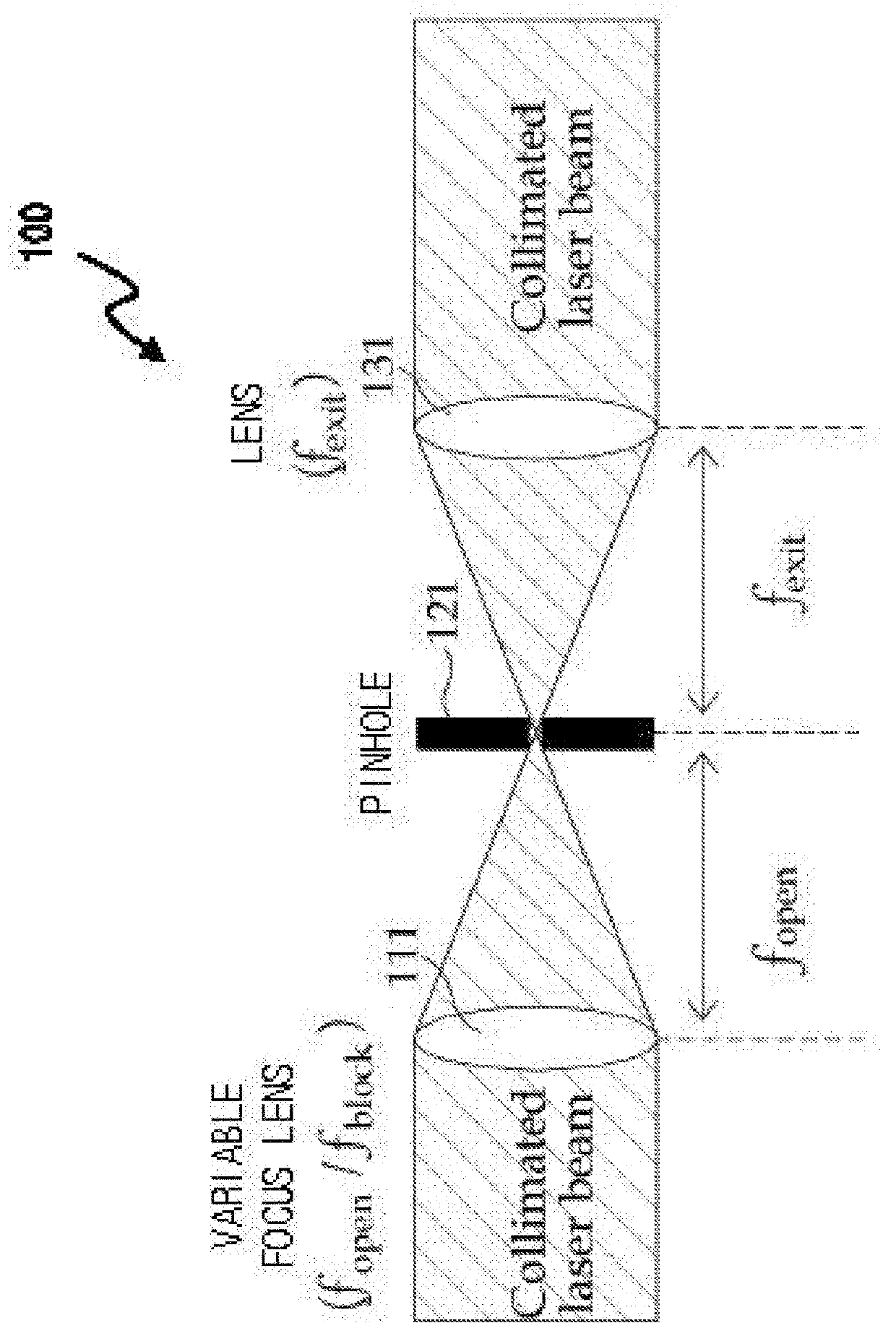
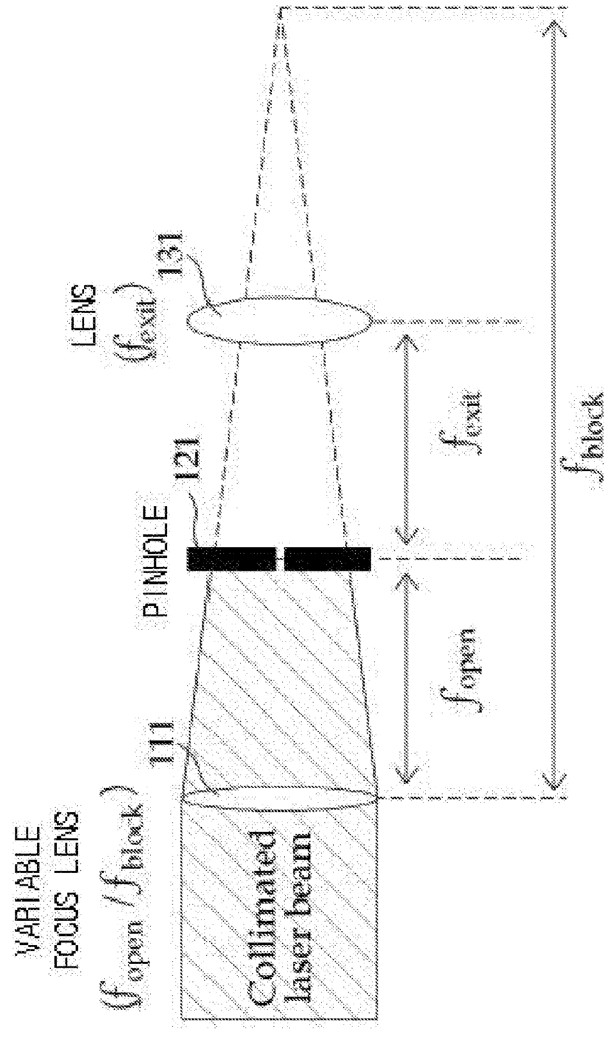
[0024]FIGS. 1 and 2 are diagrams illustrating an operation of a laser light source shutter using a variable focus lens.

[0025]The laser light source shutter 100 may include a variable focus lens 111, a pinhole 121, and an exit lens 131. The laser light source shutter 100 may transmit / block a laser light source (or a laser light) by electrically changing a focal length (or a focus) of a variable focus lens 111. Therefore, the laser light source shutter 100 may have a high light-blocking rate and a high light efficiency with a low cost without a vibration occurring in a mechanical shutter.

[0026]Referring to FIGS. 1 and 2, an operation (or an operation principle) of the laser light source shutter 100 using the variable focus lens 111 when a first focal length fopen is shorter than a second focal length fblock (i.e., fopenblock). FIG. 1 shows a case in which the laser ...


PUM


Abstract

A laser light source shutter system includes a light source, a variable focus optical element to transmit a beam emitted from the light source, a pinhole located on an optical path through which the beam travels from the variable focus optical element, and a controller to control a transmission and blocking of the beam by controlling a focal length of the variable focus optical element to be equal to a distance between the variable focus optical element and the pinhole or to be equal to other distances different from the distance. Therefore, a laser light source shutter free from vibration can be realized electronically with a low cost and a high light-blocking rate using a variable focus optical element such as a variable focus lens and a variable focus mirror.

Description

CROSS-REFERENCE TO RELATED APPLICATION(S)[0001]This application claims priority under 35 USC § 119 to Korean Patent Application No. 10-2015-0168304, filed on Nov. 11, 2015 in the Korean Intellectual Property Office (KIPO), the contents of which are incorporated herein in its entirety by reference.BACKGROUND1. Technical Field[0002]Example embodiments relate to an optical technique. More particularly, embodiments of the present inventive concept relate to an electronic shutter system.2. Description of the Related Art[0003]A shutter to control an exposure time of a laser light source may be classified as a mechanical shutter and an electronic shutter having no mechanical operation (or no mechanical motion, no mechanical movement).[0004]The mechanical shutter is inexpensive and has an excellent light-blocking rate, but the mechanical shutter has a vibration due to mechanical operation when the mechanical shutter operates such that the mechanical shutter is difficult to use in situations...

Claims


Application Information

Patent Timeline
Patent Type & Authority Applications(United States)
IPC IPC(8): G02B27/09
CPCG02B27/0955G02B27/0983H01S3/0085G02B26/02G02B26/00
Inventor HONG, JI SOOKANG, HOON JONGHONG, SUNG HEESHIN, CHOON SUNGKIM, YOUNG MIN
Owner KOREA ELECTRONICS TECH INST
Why Eureka
Try Eureka