Rotor and resolver

Active Publication Date: 2018-09-20
MINEBEAMITSUMI INC
View PDF10 Cites 1 Cited by
  • Summary
  • Abstract
  • Description
  • Claims
  • Application Information

AI Technical Summary

Benefits of technology

The invention is about a device that prevents a rotor and a resolver from being mounted incorrectly on a rotary shaft of an electric machine.

Problems solved by technology

In a manufacturing process in which the resolver is mounted on the rotary shaft of the rotary electric machine, however, a wrong type of resolver may be incorrectly mounted on the rotary shaft of the rotary electric machine.
If the wrong type of resolver mounted incorrectly has an electrical characteristic different from an electrical characteristic of the correct type of resolver to be originally mounted, however, the resolver may produce a faulty output signal.
Even with a marking system implemented in the manufacturing process to determine the correct type of resolver, a wrong type of resolver may be mounted on the rotary shaft of the rotary electric machine due to failure to check the marking.

Method used


Image

  • Rotor and resolver
  • Rotor and resolver
  • Rotor and resolver

Examples


first embodiment

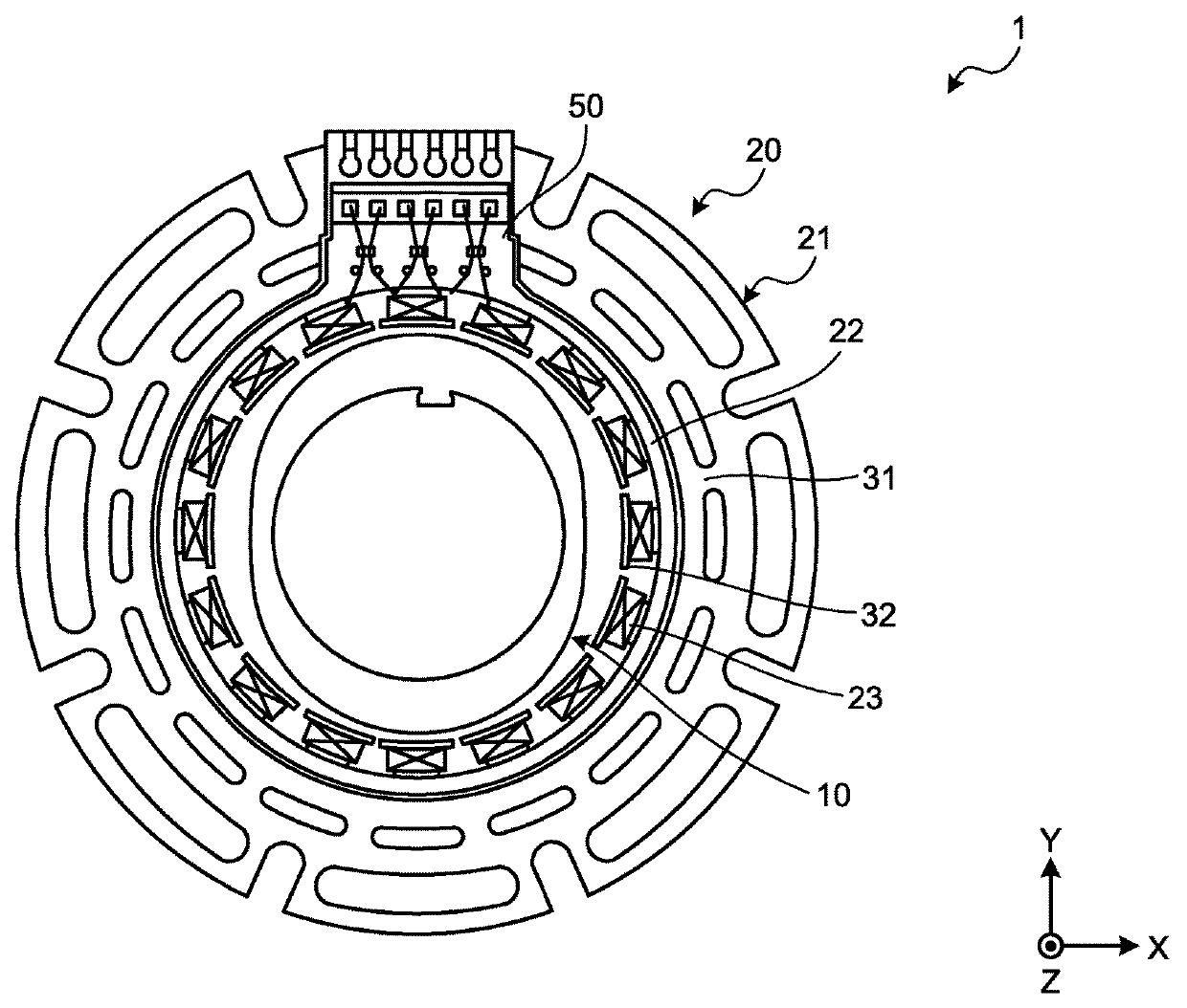
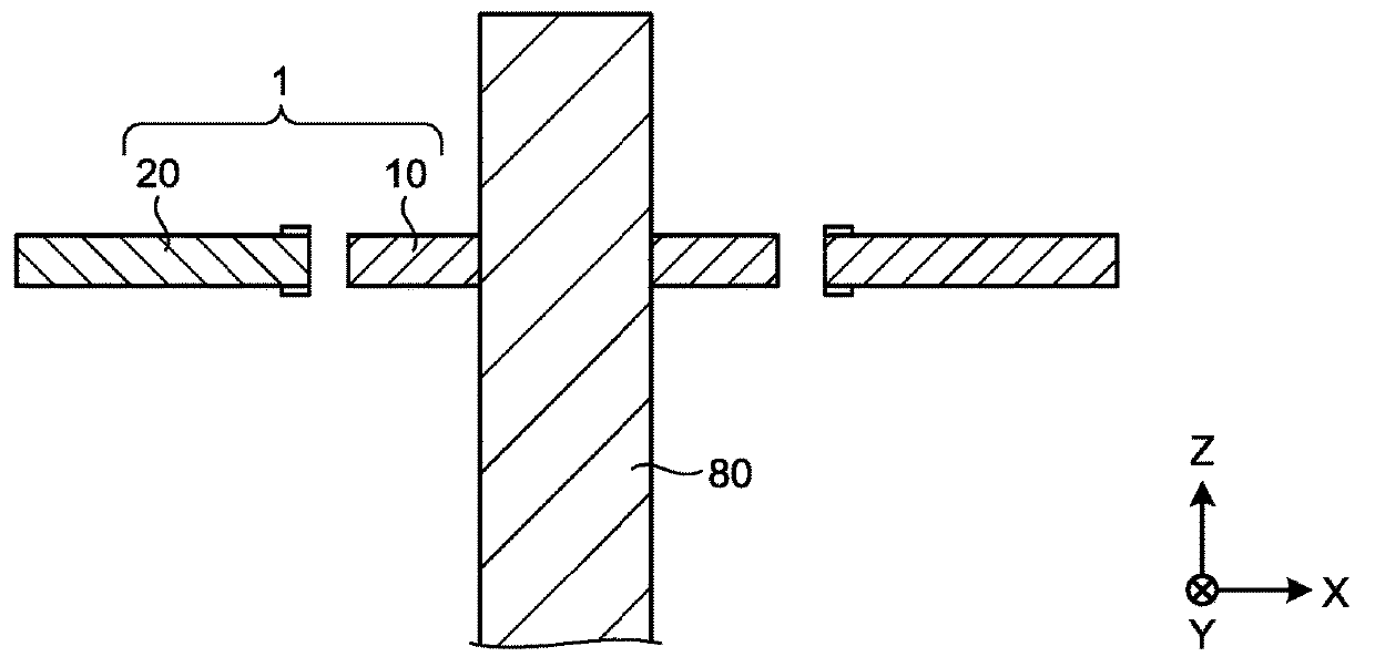
[0029]FIG. 1 is a schematic plan view of an exemplary resolver according to a first embodiment. FIG. 2 is a schematic cross-sectional view of an exemplary state in which the resolver according to the first embodiment is mounted in a rotary electric machine. As illustrated in FIG. 1, this resolver 1 according to the first embodiment is a variable reluctance (VR) resolver including a rotor 10 and a stator 20. The resolver 1 illustrated in FIG. 1 is an inner rotor type in which the rotor 10 is disposed inside the stator 20.

[0030]As illustrated in FIG. 2, the rotor 10 is mounted on a rotary shaft 80 of a rotary electric machine and rotates as the rotary shaft 80 rotates. Examples of the rotary electric machine include, but are not limited to, an AC electric motor, an AC generator, and an AC motor generator. The rotor 10 has a configuration to be detailed later.

[0031]The stator 20 includes a stator core 21, an insulator 22, and a plurality of stator coils 23. The stator core 21 includes ...

second embodiment

[0070]A resolver according to the second embodiment differs from the inner rotor type resolver 1 according to the first embodiment in that the resolver in the second embodiment is an outer rotor type.

[0071]FIG. 15 is a schematic plan view of the resolver according to the second embodiment. As illustrated in FIG. 15, this resolver 1A in the second embodiment is a VR resolver including a rotor 10A and a stator 20A. The rotor 10A is disposed outside the stator 20A.

[0072]As with the rotor 10, the rotor 10A is connected with a rotary shaft of a rotary electric machine and rotates as the rotary shaft rotates. The rotor 10A has an inner circumferential surface that is irregularly shaped with respect to a radial direction. The rotor 10A of the resolver 1A illustrated in FIG. 15 is illustrated so as to have protrusions at three places on the inner circumferential surface and to have a shaft angle multiplier of 3×. The rotor 10A may nonetheless have a shaft angle multiplier of 2× or less, or ...

third embodiment

[0081]A rotor of a resolver according to a third embodiment differs from the rotor 10 of the resolver 1 according to the first embodiment in that, whereas the rotor 10 in the first embodiment has the protrusion 12 to be fitted in the rotary shaft 80, the rotor in the third embodiment has a recess with which the rotary shaft 80 is connected. The resolver in the third embodiment, excepting the rotor, is configured similarly to the resolver 1 in the first and second embodiments and the description for the similar configurations will be omitted.

[0082]FIG. 17 is a schematic cross-sectional view of an exemplary rotor of the resolver according to the third embodiment. The example illustrated in FIG. 17 illustrates the schematic cross-section of a rotor 10B mounted on the rotary shaft 80.

[0083]As illustrated in FIG. 17, the rotor 10B includes an annular rotor main unit 11B and has a recess 18B. The recess 18B extends inward an inner circumference (inner circumferential circle) 13B of the ro...


PUM


Abstract

A rotor in one embodiment includes an annular rotor main unit and a fitting portion that extends inward or outward one of an inner circumference and an outer circumference of the rotor main unit to be connected with a rotary shaft. The fitting portion is formed at a position at which a centerline of the fitting portion is offset in parallel with respect to a normal line that is associated with a tangent line of the one of the inner circumference and the outer circumference.

Description

CROSS-REFERENCE TO RELATED APPLICATION(S)[0001]The present application claims priority to and incorporates by reference the entire contents of Japanese Patent Application No. 2017-053576 filed in Japan on Mar. 17, 2017.BACKGROUND OF THE INVENTION1. Field of the Invention[0002]The present invention relates to a rotor and a resolver.2. Description of the Related Art[0003]A resolver is known as a device for detecting an angle of rotation of a rotary electric machine such as a motor and a generator. The resolver typically includes a stator core and a rotor. The stator core includes a plurality of tooth portions extending inward toward the center from an inner circumferential side of an annularly formed stator main unit. The rotor is disposed, on the inside of the stator core, to be opposed to the tooth portions of the stator and mounted on a rotary shaft of the rotary electric machine.[0004]The rotor of the resolver has a protrusion formed on the inside thereof as a lock with respect to...

Claims


Application Information

Patent Timeline
IPC IPC(8): H02K24/00H02K1/24H02K11/21
CPCH02K24/00H02K1/246H02K11/21H02K1/28H02K2201/03G01D5/2046G01D5/24442G01D1/00
Inventor ABE, HIROSHINAKAGAWA, TAKASHI
Owner MINEBEAMITSUMI INC
Why Eureka
Try Eureka