Air-guide member for an apparatus using air flow to prepare food ingredients

a technology of air-guided components and food ingredients, which is applied in the field of air-guided components for food preparation, can solve the problems of food ingredients that might get overcooked, not always optimized cooking,

Active Publication Date: 2018-09-27
VERSUNI HLDG BV
View PDF1 Cites 66 Cited by
  • Summary
  • Abstract
  • Description
  • Claims
  • Application Information

AI Technical Summary

Benefits of technology

[0011]When an input air flow directing downwards and towards the outer part of the air-guide member, the concave air channel allows directing a portion of the input air flow towards the inner part of the air-guide member. As a result, each of the first surface receives an air flow component along its length that can be further redirected upwards thanks to the inclination of this first surface. This results in that not only the air flow is directed upwards, but also that air flowing upwards is evenly distributed between the outer part and the inner part of the air-guide member (as opposed to known air-guide member that mainly redirect air upwards in a region close to the outer part). The food ingredients can thus receive a flow of hot air having a more uniform air pressure distribution, which results in a more even cooking of the food ingredients.
[0041]When the drawer has vertical walls abutting tangentially the curved portion situated at the outer part of the air-guide member, this allows having a smooth contact of an input air flow with the air-guide member, which minimizes the loss of air speed and air pressure.

Problems solved by technology

However, although those known air-guide members helps the air flow be directed towards the food ingredients, the cooking of food ingredients is not always optimized because it happens that food ingredients are cooked non-evenly, i.e. some food ingredients remain under-cooked.
If the cooking duration is increased, some food ingredients might get over-cooked.

Method used


Image

  • Air-guide member for an apparatus using air flow to prepare food ingredients
  • Air-guide member for an apparatus using air flow to prepare food ingredients
  • Air-guide member for an apparatus using air flow to prepare food ingredients

Examples


first embodiment

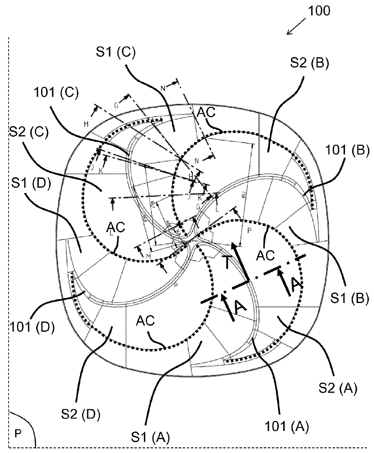
[0061]The positive angle a1 compared to the horizontal plane P, and the negative angle a2 compared to the horizontal plane P are illustrated in FIG. 3A, which depicts a vertical cross-section view A-A of an air-deflecting arm used in an air-guide member according to the invention. The vertical cross-section view A-A is taken perpendicularly compared to a tangential direction T of a top edge of the air-deflecting arms 101, as illustrated in FIG. 1. For example, the absolute value of the positive angle a1 and the negative angle a2 is in the range [10; 60] degrees compared to the horizontal plane P.

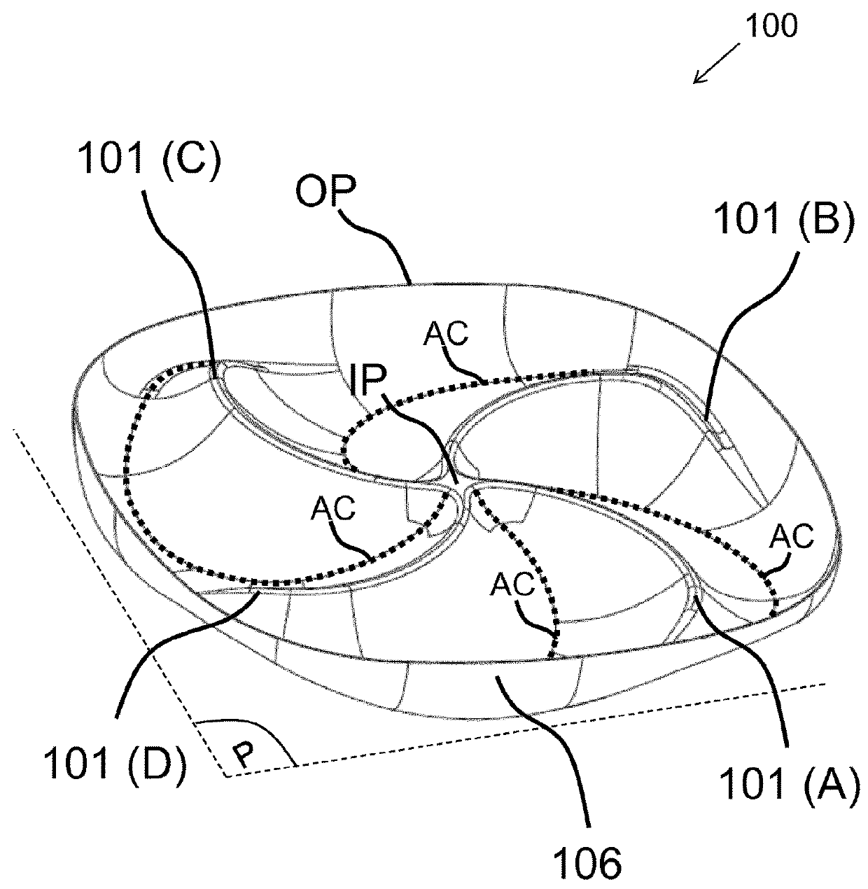
[0062]FIG. 2A depicts a three-dimensional view of an air-guide member according to the invention. It can be seen that the concave air channel AC extending between the outer part OP and the inner part IP takes the shape of a rill (i.e. a furrow, a gutter). The shape of the concave air channel AC can also be appreciated on FIG. 5A and FIG. 5B, which depict various vertical cross-section views ...

second embodiment

[0071]Advantageously, the first surface S1 and the second surface S2 have a concave curvature facing opposite the horizontal plane P. This characteristic is illustrated on FIG. 3B, which depicts a vertical cross-section view A-A of an air-deflecting arms used in an air-guide member according to the invention.

[0072]For example, the vertical projection of the bottom part of the concave air channel AC on the horizontal plane P is at equal distance between two consecutive air-deflecting arms 101.

[0073]Advantageously, the span L1 of the air-deflecting arms 101 has a value in the range [80; 100]% of the length L0 between the inner part IP and the outer part OP. This characteristic is illustrated on FIG. 6.

[0074]Advantageously, the air-deflecting arms 101 converge to the inner part IP to form an upper extremity 105 at the inner part IP having a width w1 in the range [1; 3]% of the length L0 between the inner part IP and the outer part OP. This characteristic is illustrated on FIG. 6 and FI...


PUM


Abstract

The invention relates to an air-guide member (100) for guiding an air flow (AF) in the food preparation chamber of an apparatus using the air flow (AF) to prepare food ingredients. The air-guide member (100) comprises a plurality of air-deflecting arms (101) arranged symmetrically and extending in a horizontal plane (P) between an inner part (IP) and an outer part (OP) of the air-guide member (100). The air-deflecting arms (101) comprises a first surface (S1) being inclined with a positive angle compared to the horizontal plane (P), and a second surface (S2) being inclined with a negative angle compared to the horizontal plane (P). The air-deflecting arms (101) is such that the second surface (S2) of a given air-deflecting arms (101) and the first surface (SI) of an air-deflecting arms (101) consecutive to the given air-deflecting arms (101) intersect to form a concave air channel (AC) extending between the outer part (OP) and the inner part (IP). This allows directing the air flow upwards and more evenly between the outer part and the inner part of the air-guide. The food ingredients can thus receive a flow of hot air having a more uniform air pressure distribution, which results in a more even cooking of the food ingredients.

Description

FIELD OF THE INVENTION[0001]The invention relates to an air-guide member for an apparatus using air flow to prepare food ingredients.[0002]The invention also relates to an apparatus using this air-guide member.[0003]The invention may be used in the field of food preparation, such as, for example, kitchen appliances.BACKGROUND OF THE INVENTION[0004]Air-based fryers are known apparatus for cooking food ingredients, for example for cooking vegetable (e.g. fries) or meat (e.g. chicken). With this type of appliance, the heat for preparing the food ingredients is provided by a flow of hot air circulated around the food ingredients. To facilitate hot air passes all the food ingredients placed in a food preparation chamber, some known apparatus use an air-guide member disposed in the bottom part of the food preparation chamber. Those known air-guide members direct the flow of hot air essentially upwards in the food preparation chamber. However, although those known air-guide members helps t...

Claims


Application Information

Patent Timeline
Patent Type & Authority Applications(United States)
IPC IPC(8): A47J37/06
CPCA47J37/0641A47J27/00A47J36/24
Inventor ZHANG, MINGSHUOKOWALEWSKI, ANDREASBRENNA, CLAUDIOSAUER, STEFAN HANS
Owner VERSUNI HLDG BV
Why Eureka
Try Eureka