
Vehicle-mounted heat utilization device

a heat utilization device and vehicle body technology, applied in vehicle heating/cooling devices, vehicle components, transportation and packaging, etc., can solve the problems of reducing fuel efficiency, and achieve the effect of heating the vehicle interior more quickly and without increasing the warmup operation tim

Inactive Publication Date: 2018-09-27
TOYOTA JIDOSHA KK +1
View PDF4 Cites 8 Cited by
  • Summary
  • Abstract
  • Description
  • Claims
  • Application Information

AI Technical Summary

Benefits of technology

The present invention is about a device that can heat up a vehicle faster in the cold season without making the warm-up process take longer. The device works by connecting two fluid circuits, one for heating the vehicle and one for cooling it. When the two circuits are connected, the device utilizes two heat sources to heat the fluid, which then heats up the vehicle interior. This way, the vehicle interior can get hot quicker without needing more time to warm up.

Problems solved by technology

In addition, according to the air conditioner disclosed in Japanese Patent Application Publication No. 6-219150 (JP 6-219150 A), because the heat of the coolant, heated by the engine, is used for vehicle interior heating during the warmup operation in the cold season, the warmup operation time is increased and the fuel efficiency is decreased due to a mechanical loss.

Method used


Image

  • Vehicle-mounted heat utilization device
  • Vehicle-mounted heat utilization device
  • Vehicle-mounted heat utilization device

Examples


first embodiment

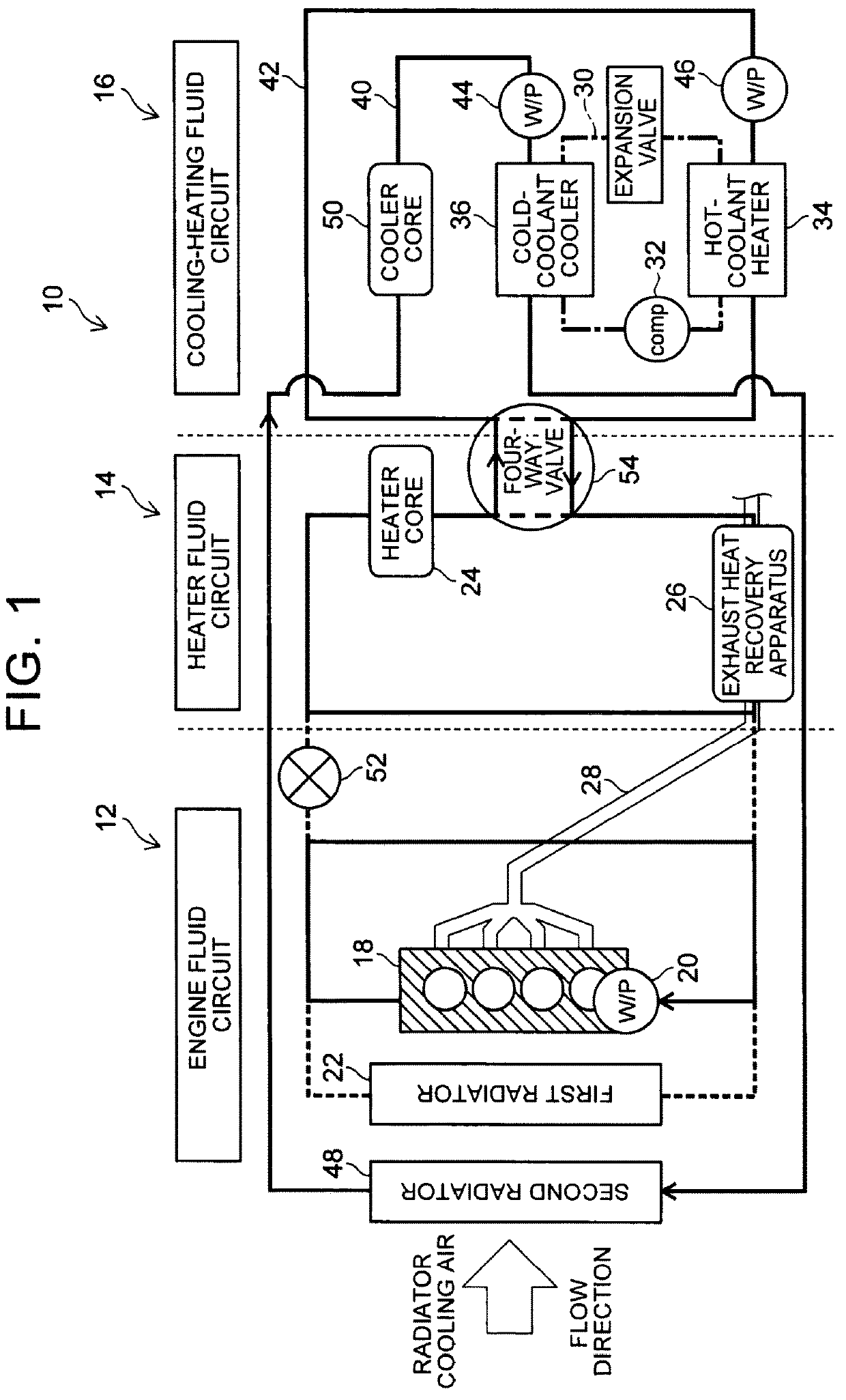
[0040]First, a vehicle-mounted heat utilization device in a first embodiment is described below. FIG. 1 is a diagram showing a general configuration of the vehicle-mounted heat utilization device in the first embodiment.

[0041]A vehicle-mounted heat utilization device 10 in this embodiment includes an engine fluid circuit 12, a heater fluid circuit 14, and a cooling-heating fluid circuit 16 as shown in FIG. 1. Coolant, one type of fluid, circulates in each of the fluid circuits. Although coolant (such as antifreeze fluid) is used as the fluid in this embodiment, other fluids such as water may also be used.

[0042]The engine fluid circuit 12 is a circulation path in which coolant circulates along the circulation path that cools an engine 18. In this circulation path, the coolant is circulated by a water pump (W / P) 20. In the engine fluid circuit 12, a first radiator 22, which works as a first heat exchanger, is connected via a thermostat, not shown, and the coolant circulates in the fir...

second embodiment

[0074]Next, a vehicle-mounted heat utilization device 11 in a second embodiment is described below. FIG. 5 is a diagram showing a general configuration of the vehicle-mounted heat utilization device in the second embodiment. For the same configuration as that in the first embodiment, the same reference numeral is used and the detailed description is omitted.

[0075]The vehicle-mounted heat utilization device 11 in this embodiment is a modification of the first embodiment with the basic configuration similar to that of the vehicle-mounted heat utilization device 10 in the first embodiment. The vehicle-mounted heat utilization device 11 differs from the vehicle-mounted heat utilization device 10 in the first embodiment in that the hot coolant circuit 42 of the cooling-heating fluid circuit 16 further includes an inverter 56 that is an on-vehicle heat receiving apparatus.

[0076]In this embodiment, the cooling-heating fluid circuit 16 has an on-vehicle heat receiving apparatus, such as the...

third embodiment

[0098]Next, a vehicle-mounted heat utilization device 13 in a third embodiment is described below. FIG. 9 is a diagram showing a general configuration of the vehicle-mounted heat utilization device in the third embodiment. For the same configuration as that in the first embodiment, the same reference numeral is used and the detailed description is omitted.

[0099]The vehicle-mounted heat utilization device 13 in this embodiment is a modification of the first embodiment with the basic configuration similar to that of the vehicle-mounted heat utilization device 10 in the first embodiment. The vehicle-mounted heat utilization device 13 differs from the vehicle-mounted heat utilization device 10 in the first embodiment in that the connection of the second radiator can be selectively switched between the cold coolant circuit 40 and the hot coolant circuit 42.

[0100]In this embodiment, three-way valves 68 are provided as shown in FIG. 9, one before the second radiator 48 and the other after ...


PUM


Abstract

A vehicle-mounted heat utilization device (10) includes: an engine fluid circuit (12) in which fluid circulates to cool an engine (18); a heater fluid circuit (14) that passes through an exhaust heat recovery apparatus (26) that recovers a heat of exhaust gas (28) and a vehicle-interior heat exchanger (24) for radiating a heat of the fluid into a vehicle interior; a cooling-heating fluid circuit (16) that passes through a radiating heat exchanger (34), the radiating heat exchanger being included in a refrigeration cycle (30) in which refrigerant is compressed by a compressor (32) and the compressed refrigerant is expanded; a first switching unit (52) that is configured to selectively switch a state of the engine fluid circuit (12) and the heater fluid circuit (14) between a connected and a disconnected state; a second switching unit (54) that is configured to selectively switch a state of the heater fluid circuit (14) and the cooling-heating fluid circuit (16) between a connected state and a disconnected state.

Description

BACKGROUND OF THE INVENTION1. Field of the Invention[0001]The present invention relates to a vehicle-mounted heat utilization device.2. Description of Related Art[0002]Japanese Patent Application Publication No. 6-219150 (JP 6-219150 A) proposes an air conditioner that circulates fluid in the refrigerant cycle, in which an evaporator and a condenser are provided, to cause the fluid to receive or absorb the refrigerant heat with the use of a heat exchanger. More specifically, an air conditioner is disclosed that circulates fluid between the evaporator and the air conditioning radiator and between the condenser and the outside radiator in the summer, and between the evaporator and the outside radiator and between the condenser and the air conditioning radiator in the winter.SUMMARY OF THE INVENTION[0003]According to the air conditioner disclosed in Japanese Patent Application Publication No. 6-219150 (JP 6-219150 A), the vehicle interior can be heated in the winter using a heat source...

Claims


Application Information

Patent Timeline
IPC IPC(8): B60H1/00B60H1/02B60H1/03
CPCB60H1/00885B60H1/025B60H1/03B60H2001/00928B60H1/00899B60H1/32284
Inventor ONISHI, YOICHISHIMPO, YOSHIKAZUMURATA, TOSHIOTANIGUCHI, SHINICHIKOMITSU, HIDEYUKIOZAWA, IKUOENOMOTO, NORIHIKOSAIDA, KAZUNORIKAKEHASHI, NOBUHARU
Owner TOYOTA JIDOSHA KK
Learn More