Depth based foveated rendering for display systems

Active Publication Date: 2018-09-27
MAGIC LEAP
View PDF2 Cites 152 Cited by
  • Summary
  • Abstract
  • Description
  • Claims
  • Application Information

AI Technical Summary

Benefits of technology

[0019]According to some other embodiments, a display system for projecting images to an eye of a user may include an eyepiece. The eyepiece may include a waveguide, and an in-coupling grating optically coupled to the waveguide. The display system may further include a first image source configured to project a first light beam associated with a first image stream. The first image stream may have a first field of view and may be incident on a first surface of the in-coupling grating. A portion of the first light beam may be coupled into the waveguide by the in-coupling grating for positioning the first image stream in a fixed position to the eye of the user. The display system may further include a second image source configured to project a second light beam associated with a second image stream. The second image stream may have a second field of view that is narrower than the first field of view. The display system may further include a scanning mirror configured to receive and reflect the second light beam such that the second light beam is incident on a second surface of the in-coupling grating opposite to the first surface thereof. A portion of the second light beam may be coupled into the waveguide by the in-coupling grating. The display system may further include an eye-gaze tracker configured to detect movement of the eye of the user, and control circuitry in communication with the eye gaze tracker and the scanning mirror. The control circuitry may be configured to position the scanning mirror such that a position of the second image stream is moved in accordance with the detected movement of the eye of the user.
[0020]According to some other embodiments, a display system for projecting images to an eye of a user may include an eyepiece. The eyepiece may include a waveguide, and an in-coupling grating optically coupled to the waveguide. The display system may further include an image source configured to project a first light beam associated with a first image stream in a first polarization, and a second light beam associated with a second image stream in a second polarization different from the first polarization. The first image stream may have a first field of view and the second image stream may have a second field of view that is narrower than the first field of view. The first light beam and the second light beam may be multiplexed. The display system may further include a polarization beam splitter configured to receive and reflect the first light beam along a first optical path, and receive and transmit the second light beam along a second optical path. The display system may further include a first optical reflector positioned along the first optical path and configured to receive and reflect the first light beam such that the first light beam is incident on a first surface of the in-coupling grating. A portion of the first light beam may be coupled into the waveguide by the in-coupling grating for positioning the first image stream in a fixed position to the eye of the user. The display system may further include a scanning mirror disposed along the second optical path and configured to receive and reflect the second light beam, and a second optical reflector positioned along the second optical path downstream from the scanning mirror. The second optical reflector may be configured to receive and reflect the second light beam such that the second light beam is incident on a second surface of the in-coupling grating opposite the first surface thereof. A portion of the second light beam may be coupled into the waveguide by the in-coupling grating. The display system may further include an eye-gaze tracker configured to detect movement of the eye of the user, and control circuitry in communication with the eye gaze tracker and the scanning mirror. The control circuitry may be configured to position the scanning mirror such that a position of the second image stream is moved in accordance with the detected movement of the eye of the user.
[0021]According to some other embodiments, a display system for projecting images to an eye of a user may include a waveguide, an image source configured to project a first light beam associated with a first image stream in a first polarization and a second light beam associated with a second image stream in a second polarization different from the first polarization. The first image stream may have a first field of view, and the second image stream having a second field of view that is narrower than the first field of view. The first light beam and the second light beam may be multiplexed. The display system may further include a polarization beam splitter configured to receive and reflect the first light beam along a first optical path, and to receive and transmit the second light beam along a second optical path. The display system may further include a first in-coupling prism positioned along the first optical path and adjacent a first surface of the waveguide. The first in-coupling prism may be configured to couple a portion of the first light beam into the waveguide for positioning the first image stream in a fixed position to the eye of the user. The display system may further include a scanning mirror disposed along the second optical path and configured to receive and reflect the second light beam. The display system may further include a second in-coupling prism positioned along the second optical path downstream from the scanning mirror and adjacent a second surface of the waveguide opposite to the first surface of the waveguide. The second in-coupling prism may be configured to couple a portion of the second light beam into the waveguide. The display system may further include an eye-gaze tracker configured to detect movement of the eye of the user, and control circuitry in communication with the eye gaze tracker and the scanning mirror. The control circuitry may be configured to position the scanning mirror such that a position of the second image stream is moved in accordance with the detected movement of the eye of the user
[0022]According to an embodiment, a display system for projecting images to an eye of a user includes an image source. The image source can be configured to project a first light beam associated with a first image stream in a first polarization, and a second light beam associated with a second image stream in a second polarization different from the first polarization. The first image stream can have a first field of view, and the second image stream can have a second field of view that is narrower than the first field of view. The first light beam and the second light beam can be multiplexed. The display system can further include a polarization beam splitter. The polarization beam splitter can be configured to receive and reflect the first light beam along a first optical path toward a viewing assembly for positioning the first image stream in a fixed position to the eye of the user, and receive and transmit the second light beam along a second optical path. The display system can further include a scanning mirror disposed along the second optical path and configured to receive and reflect the second light beam toward the viewing assembly. The display system can further include an eye-gaze tracker configured to detect movement of the eye of the user, and control circuitry in communication with the eye gaze tracker and the scanning mirror. The control circuitry can be configured to position the scanning mirror such that a position of the second image stream is moved in accordance with the detected movement of the eye of the user.
[0023]According to another embodiment, a display system for projecting images to an eye of a user include an image source. The image source can be configured to project a first light beam associated with a first image stream and a second light beam associated with a second image stream. The first image stream can have a first field of view, and the second image stream can have a second field of view that is narrower than the first field of view. The first light beam and the second light beam can be multiplexed. The display system can further include a scanning mirror configured to receive and reflect the first light beam and the second light beam toward a viewing assembly for projecting the first image stream and the second image stream. The display system can further include an eye-gaze tracker configured to detect movement of the eye of the user, and control circuitry in communication with the eye gaze tracker and the scanning mirror. The control circuitry can be configured to position the scanning mirror such that a position of the first image stream and a position of the second image stream are moved in accordance with the detected movement of the eye of the user. The display system can further include a switchable optical element disposed in an optical path of the first light beam and the second light beam. The switchable optical element can be configured to be switched to a first state for the first light beam such that the first light beam is angularly magnified by a first angular magnification, and be switched to a second state for the second light beam such that the second light beam is angularly amplified by a second angular magnification that is less than the first angular magnification.

Problems solved by technology

Because the human visual perception system is complex, it is challenging to produce AR technology that facilitates a comfortable, natural-feeling, rich presentation of virtual image elements amongst other virtual or real-world imagery elements.

Method used


Image

  • Depth based foveated rendering for display systems
  • Depth based foveated rendering for display systems
  • Depth based foveated rendering for display systems

Examples


Embodiment Construction

[0105]Rendering virtual content for augmented and virtual display systems is computationally intensive. Among other things, the computational intensity may undesirably use large amounts of memory, cause high latency, and / or may require the use of powerful processing units that may have high cost and / or high energy-consumption.

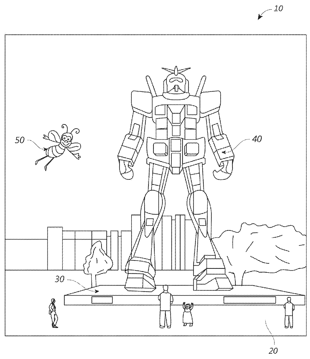
[0106]In some embodiments, methods and systems conserve computational resources, such as memory and processing time, by reducing the resolution of virtual content positioned at locations away from the fixation point of the user's eyes. For example, the system may render virtual content at a relative high (e.g., a highest) resolution at or proximate a fixation point of the user's eyes, while utilizing one or more lower resolutions for virtual content away from the fixation point. The virtual content is presented by a display system that can display virtual content on a plurality of different depths (e.g., a plurality of different depth planes, such as two or mor...


PUM


Abstract

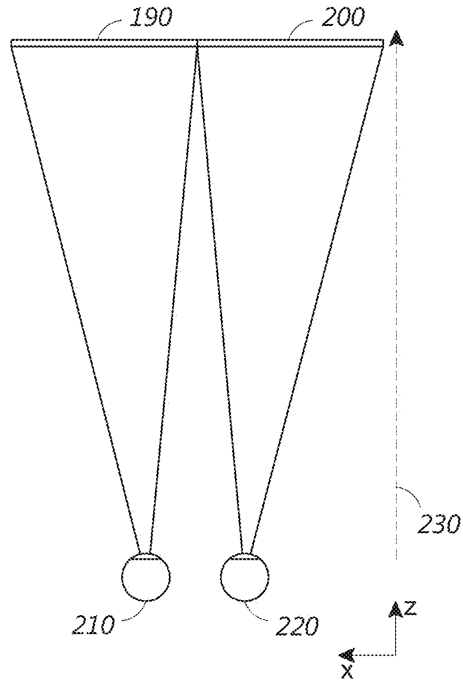
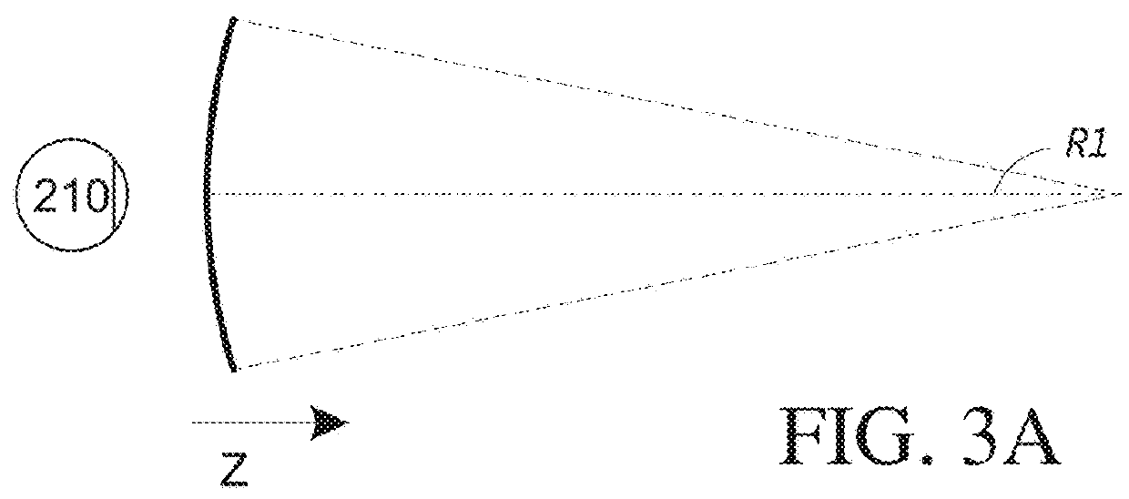
Methods and systems for depth-based foveated rendering in the display system are disclosed. The display system may be an augmented reality display system configured to provide virtual content on a plurality of depth planes using different wavefront divergence. Some embodiments include monitoring eye orientations of a user of a display system based on detected sensor information. A fixation point is determined based on the eye orientations, the fixation point representing a three-dimensional location with respect to a field of view. Location information of virtual objects to present is obtained, with the location information indicating three-dimensional positions of the virtual objects. Resolutions of at least one virtual object is adjusted based on a proximity of the at least one virtual object to the fixation point. The virtual objects are presented to a user by display system with the at least one virtual object being rendered according to the adjusted resolution.

Description

PRIORITY CLAIM[0001]This application claims priority to U.S. Provisional Application No. 62 / 644,365 filed on Mar. 16, 2018; U.S. Provisional Application No. 62 / 475,012 filed on Mar. 22, 2017. U.S. Provisional Application No. 62 / 486,407 filed on Apr. 17, 2017, and U.S. Provisional Application No. 62 / 539,934 filed on Aug. 1, 2017. The above-recited patent applications are hereby incorporated by reference in their entirety for all purposes.INCORPORATION BY REFERENCE[0002]This application incorporates by reference the entirety of each of the following patent applications and publications: U.S. application Ser. No. 14 / 555,585 filed on Nov. 27, 2014, published on Jul. 23, 2015 as U.S. Publication No. 2015 / 0205126; U.S. application Ser. No. 14 / 690,401 filed on Apr. 18, 2015, published on Oct. 22, 2015 as U.S. Publication No. 2015 / 0302652; U.S. application Ser. No. 14 / 212,961 filed on Mar. 14, 2014, now U.S. Pat. No. 9,417,452 issued on Aug. 16, 2016; U.S. application Ser. No. 14 / 331,218 fi...

Claims


Application Information

Patent Timeline
Patent Type & Authority Applications(United States)
IPC IPC(8): G02B27/01G02B27/00G06T19/00
CPCG02B27/0172G02B27/0093G02B2027/0178H04N13/279G02B2027/0147H04N13/341G06T19/006G06F3/013G06T7/246H04N13/383H04N13/398G02B2027/0134G02B2027/0185H04N2213/002H04N13/395H04N13/344G06T15/00G06T2210/36G06F3/011G06F3/012G06F3/0346
Inventor YEOH, IVAN LI CHUENEDWIN, LIONEL ERNESTSAMEC, NICOLE ELIZABETHROBAINA, NASTASJA U.MATHUR, VAIBHAVDALRYMPLE, TIMSCHAEFER, JASONCARLISLE, CLINTONCHENG, HUI-CHUANOH, CHULWOOPREMYSLER, PHILIPZHANG, XIAOYANGCARLSON, ADAM
Owner MAGIC LEAP
Why Eureka
Try Eureka