
Harvesting tumbler

a technology of harvesting tumblers and tumblers, which is applied in the field of tumblers, can solve the problems of reducing the yield rate of the plant material, so as to achieve the effect of increasing the yield rate and increasing the yield ra

Active Publication Date: 2018-10-04
ETEROS TECH INC
View PDF3 Cites 9 Cited by
  • Summary
  • Abstract
  • Description
  • Claims
  • Application Information

AI Technical Summary

Benefits of technology

The present invention aims to overcome the disadvantages of conventional tumblers. The technical effects of the invention include increased robustness, reduced likelihood of deformation during maintenance, and improved cleaning efficiency. The invention includes an annular piston and a first grating segment retainer that move axially away from a second grating segment retainer when the fluid pressure in the annular cylinder increases. This allows for improved clearance between the tumbler and the cutting blade during operation.

Problems solved by technology

Firstly, conventional tumblers formed from an initially flat sheet of metal are generally not perfectly round.
Disadvantageously, imperfections in the cylindrical shape of the cylinder result in a greater distance between the cutting blade and the tumbler, leaving the plant material “shaggier” with more leaf material than desired.
Secondly, conventional tumblers are relatively delicate rather than robust, in the sense that they can easily be accidentally deformed during routine cleaning or related handling.
Tumblers frequently clog with resin and other plant material and need to be removed for cleaning and maintenance.
Any such accidental deformation during maintenance will aggravate the first disadvantage above, requiring an increased clearance between the tumbler and the cutting blade to avoid contact between the two during operation.
Thirdly, in a conventional tumbler, the surface area occupied by solid sheet metal is typically comparable to or even larger than the surface area occupied by the slots, so that the leaf material can only get through perhaps half of the surface area of the overall cylinder.
As a result, relatively long flow-through or dwell times are required, with the buds spending more time in the tumbler, before the leaf material will be adequately trimmed.
However, longer flow-through times are undesirable for some crops: for medical marijuana for example, if the buds spend longer in the tumbler, a commensurately greater amount of the active ingredients (e.g. tetrahydrocannabinol (THC), cannabidiol (CBD), etc.) will be inadvertently shaken off the buds and sucked away by the vacuum, along with the trimmed leaf material.
The ability to address this problem by simply making the slots occupy a greater percentage of the area of the cylinder is inherently limited by the design of conventional tumblers: such an approach tends to weaken the strength of the tumbler, thereby aggravating the second disadvantage discussed in the preceding paragraph.
Fourthly, the manufacture of conventional tumblers is labour-intensive and therefore expensive, involving multiple different processes.
In addition, the grating segments tend to have a smaller diameter than the thickness of conventional sheet metal tumblers, thus further reducing the clearance between the tumbler inner diameter and the cutting blade.

Method used


Image

  • Harvesting tumbler
  • Harvesting tumbler
  • Harvesting tumbler

Examples


first embodiment

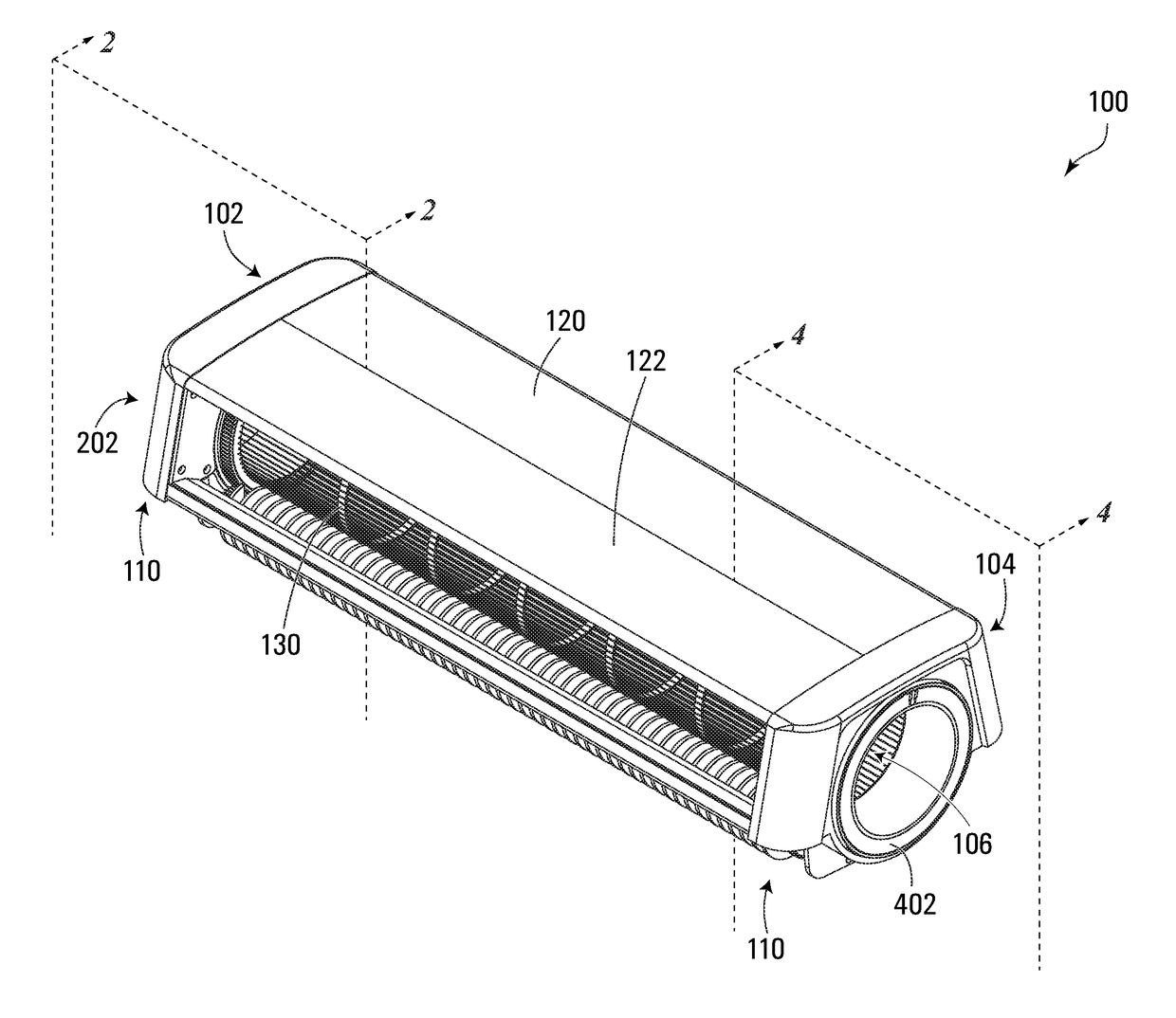
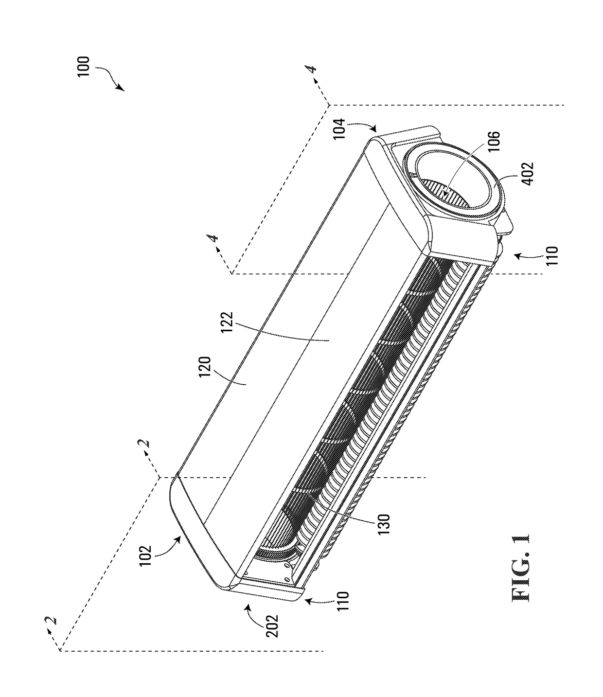
[0038]Referring to FIGS. 1-7, a harvesting tumbler apparatus according to the invention is shown generally at 100 in FIG. 1. In this embodiment, the tumbler apparatus 100 includes first and second spaced apart grating segment retainers 202 and 402 shown in FIGS. 2-3 and 4-5, respectively, which in this embodiment are disposed at first and second opposite end regions 102 and 104 of the tumbler apparatus 100 shown in FIG. 1.

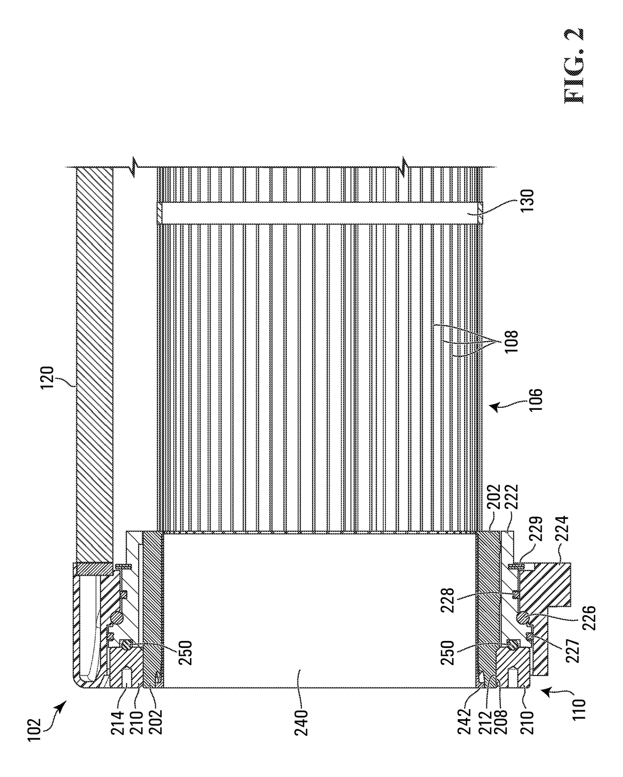
[0039]In this embodiment, the tumbler apparatus 100 further includes a tumbler grating shown generally at 106 including a plurality of resiliently tensionable grating segments 108 such as those shown in FIGS. 2 and 4, connected to the first and second grating segment retainers 202 and 402. In this embodiment, the resiliently tensionable grating segments 108 extend from each of the first and second grating segment retainers 202 and 402 in a spaced apart circular arrangement.

[0040]In this embodiment, the tumbler apparatus 100 further includes a tension mechanism show...

second embodiment

[0044]In this embodiment, the plurality of cord segments that serve as the resiliently tensionable grating segments 108 are all segments of a single continuous cord. Alternatively, as discussed below in connection with the second embodiment, each of the cord segments may be a separate cord.

[0045]Also in this embodiment, each individual resiliently tensionable grating segment 108 has a cylindrical shape when under tension.

Grating Segment Retainers

[0046]Referring to FIGS. 3 and 5, in this embodiment the first grating segment retainer 202 and the second grating segment retainer 402 are similar in some ways but different in others.

[0047]In this embodiment, the first grating segment retainer 202 is annular. A plurality of recessed axially extending channels 204 are defined in an inner surface of the retainer 202, each channel configured to accommodate a respective one of the plurality of resiliently tensionable grating segments 108. The retainer 202 further includes a plurality of tabs 2...

third embodiment

[0099]In this regard, referring to FIG. 12, in a third embodiment, the tension mechanism includes a fluid tension mechanism shown generally at 1200, configured to vary an axial distance between the two grating segment retainers in response to varying fluid pressure. In this embodiment, the threaded torquable tension ring 210 is omitted. Instead, the tension mechanism 1200 includes a fluid pressure tension ring shown generally at 1202. In this embodiment, the fluid pressure tension ring 1202 is pneumatic, although alternatively a hydraulic tension ring may be substituted.

[0100]More particularly, in this embodiment the fluid pressure tension ring 1202 of the tension mechanism 1200 includes an annular cylinder 1204 and an annular piston 1206 configured to move axially out of or into the annular cylinder 1204 in response to increasing or decreasing fluid pressure within the cylinder 1204, respectively.

[0101]More particularly still, in this embodiment the annular cylinder 1204 and the an...


PUM


Abstract

A harvesting tumbler apparatus includes first and second spaced apart grating segment retainers, and a tumbler grating including a plurality of resiliently tensionable grating segments connected to the first and second grating segment retainers. The resiliently tensionable grating segments extend from each of the first and second grating segment retainers in a spaced apart circular arrangement. The tumbler apparatus further includes a tension mechanism configured to apply a sufficient tension force to the resiliently tensionable grating segments to cause the grating to form a cylindrical shape. In illustrative embodiments, the resiliently tensionable grating segments may include flexible cord segments.

Description

FIELD OF THE INVENTION[0001]The present invention relates to agricultural harvesting equipment, and more particularly to tumblers.BACKGROUND OF THE INVENTION[0002]Some types of agricultural crops are harvested primarily for their flowers or for their pre-flowering buds (embryonic shoots). Examples of such crops include hops (one of the four main ingredients in beer), medical marijuana, or recreational marijuana in jurisdictions where it is legal, for example.[0003]The harvesting of such crops typically includes separating the desirable flowers or buds from undesirable leaf material. Conventionally, this is achieved by causing harvested buds to travel longitudinally through the inside of a tumbler, which is conventionally a rotating cylinder formed of sheet metal with slots cut out of it. As the tumbler rotates, a vacuum underneath the tumbler applies a suction force, which causes some of the leaves to protrude outward through the slots into the cylinder and into the path of a sharp ...

Claims


Application Information

Patent Timeline
IPC IPC(8): A01G17/02A01D46/02A01G1/00
CPCA01G22/00A01D46/02A01G17/02A01G3/00A01G2003/005A01G3/08
Inventor MCKELLAR, AARONMCKELLAR, AMANDAINGRAM, ERIKKLOSSOK, RUDIHEYWOOD, JOEO'SULLIVAN, DAVID
Owner ETEROS TECH INC
Learn More