Coil, and magnetic stimulation device using the coil

a magnetic stimulation device and coil technology, applied in the field of coils and magnetic stimulation devices, can solve the problems of device only being used in well equipped medical facilities, unwilling to have it performed, and inability to witness the results of treatment using medicines, etc., to achieve wide induced electrical fields, keep inductance to, and generate an induced electrical field with respect to applied current.

Active Publication Date: 2018-10-04
THE UNIV OF TOKYO
View PDF4 Cites 3 Cited by
  • Summary
  • Abstract
  • Description
  • Claims
  • Application Information

AI Technical Summary

Benefits of technology

[0054]According to the present invention it is possible to provide a coil with which efficiency of generating an induced electrical field with respect to applied current is high even if design of area of an actuation part is widened so as to obtain a comparatively wide induced electrical field, and that can also keep inductance to a low value.
[0055]Also, according to the present invention, sinc

Problems solved by technology

With these types of illness, there are cases where results are not witnessed with treatment using medicines.
However, this method of treatment requires a craniotomy, and so many patients are unwilling to have it performed.
However, a conventional magnetic stimulation device has a weight of about 70 kg, and at the time of installation electrical work is necessary in order to be able to supply electrical power from a 200 V power supply, which means that the device can only be used in well equipped medical facilities.
This means that at a stimulation position that has been guided by using a navigation system, if a treatment device that carries out magnetic stimulation with a figure-8 coil is used, there is a possibility that a region that is to be radiated (optimum stimulation position) will not be within the effective stimulation range of the treatment coil, and so it w

Method used


Image

  • Coil, and magnetic stimulation device using the coil
  • Coil, and magnetic stimulation device using the coil
  • Coil, and magnetic stimulation device using the coil

Examples


second embodiment

[0168]Next, a magnetic stimulation device of a second embodiment of the present invention will be described with reference to FIG. 25 to FIG. 27. It should be noted that elements that are basically common to the magnetic stimulation device of previous embodiments that have already been described will be assigned the same reference numerals, to avoid duplicated description.

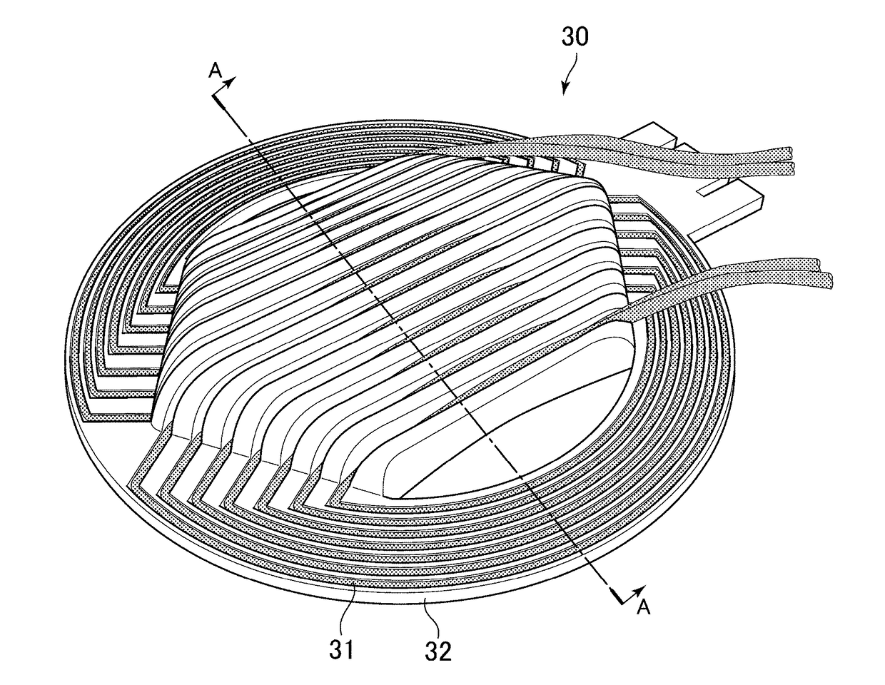
[0169]With the magnetic stimulation device of this embodiment, a contact section 321 constituting a support 32 of the application part 30 is configured so as to be substantially flat and circular. A flange section 322 is formed extending from a peripheral edge of the contact section 321 so as to be inclined towards the head 1 (refer to FIG. 26 and FIG. 27).

[0170]In a case where a bottom surface of the contact section 321 was made the spherical surface, as shown in FIG. 6, then in the event that curvature of the head 1 was smaller than the curvature of the bottom surface of the contact section 321 (that is, in the e...

third embodiment

[0174]Next, a magnetic stimulation device of a third embodiment of the present invention will be described with reference to FIG. 29 to FIG. 30. It should be noted that elements that are basically common to the magnetic stimulation device of the second embodiment that has already been described will be assigned the same reference numerals, to avoid duplicated description.

[0175]With the magnetic stimulation device of this embodiment, a contact section 321 constituting a support 32 of the application part 30 is configured so as to be substantially flat and elliptical.

[0176]A modified example of the device of this third embodiment is shown in FIG. 32. With the above described third embodiment, an angle formed by the contact section 321 and the flange section 322 is generally made angle θ1 (refer to FIG. 30). Conversely, with this modified example, this angle differs with position such that θ1>θ2.

[0177]Other structures and advantages of this third embodiment are the same as those of the...

fourth embodiment

[0178]Next, a magnetic stimulation device of a fourth embodiment of the present invention will be described with reference to FIG. 33 to FIG. 35. It should be noted that elements that are basically common to the magnetic stimulation device of the second embodiment that has already been described will be assigned the same reference numerals, to avoid duplicated description.

[0179]With the magnetic stimulation device of this embodiment, the flange section 322 is constructed extending from a peripheral edge of the contact section 321 in a direction that is the same as the extension direction of the contact section 321. In this way, with this embodiment, the whole of the support 32 is formed in a single disk shape.

[0180]Other structures and advantages of this fourth embodiment are the same as those of the previously described second embodiment, and so more detailed description has been omitted.


PUM


Abstract

A coil 31 has 1st to Nth turns 311 to 31N. The 1st to Nth turns 311 to 31N are respectively provided with actuation parts 311a for current in one direction to flow, and connection parts 311b for current in the opposite direction to the one direction to flow. The plurality of actuation parts 311a are arranged substantially parallel to each other, and are arranged along a surface of an object 1 or a surface that approximates to the surface of the object 1. A plurality of connection parts 311b are arranged within a space in which the connection parts do not face the surface of the object 1 over the actuation parts 311a of the 1st to Nth turns, and the connection parts are positioned at the sides with respect to the extension direction of the actuation parts 311a.

Description

TECHNICAL FIELD[0001]The present invention relates to a coil, and to a magnetic stimulation device that uses this coil.BACKGROUND ART[0002]Transcranial Magnetic Stimulation (TMS) is a method of causing current flow within the brain by electromagnetic induction, and stimulating neurons. According to this method, as shown in FIG. 1 to FIG. 3, by applying an alternating current or a given current waveform to a stimulation coil that has been placed above a person's scalp, a variable magnetic field is generated, and the effect of that variable magnetic field is to induce, within the brain, eddy current in a reverse direction to coil current, and nerve impulses is generated as a result of stimulation of neurons by this eddy current. This type of Transcranial Magnetic Stimulation is being used in clinical laboratory tests and cerebral function research, including measurement of nerve conduction velocity.[0003]In recent years, magnetic stimulation has been gathering attention as a therapeut...

Claims


Application Information

Patent Timeline
IPC IPC(8): A61N2/00A61N2/02
CPCA61N2/006A61N2/02A61N1/40
Inventor SEKINO, MASAKIYAMAMOTO, KEITAKAWASAKI, YUTA
Owner THE UNIV OF TOKYO
Why Eureka
Try Eureka