
Pneumatic Tire

a technology of pneumatic tires and ribs, applied in the field of pneumatic tires, can solve the problems of reducing rolling resistance, affecting the performance of pneumatic tires, etc., and achieves the effect of suppressing excessive deformation suppressing rib tear occurrence, and suppressing the damage of the shoulder land portion 23

Inactive Publication Date: 2018-10-04
THE YOKOHAMA RUBBER CO LTD
View PDF3 Cites 2 Cited by
  • Summary
  • Abstract
  • Description
  • Claims
  • Application Information

AI Technical Summary

Benefits of technology

The present technology provides a pneumatic tire that can prevent damage to the tire's tread rubber while also reducing rolling resistance and maintaining its wear resistance performance.

Problems solved by technology

When a heavy duty pneumatic tire swivels or runs onto a curb, the land portion may incur damage or excessive deformation.
When the land portion incurs excessive deformation, cracks may occur in an inner surface of the circumferential main groove, and the tread rubber may partially tear off.
Further, in the heavy duty pneumatic tire, a reduction in rolling resistance is required.
However, when the volume of tread rubber is decreased, the wear resistance performance of the pneumatic tire decreases.

Method used


Image

  • Pneumatic Tire
  • Pneumatic Tire
  • Pneumatic Tire

Examples


examples

[0191]Tires that satisfy and tires that do not satisfy the conditions of feature 1, feature 16, feature 22, feature 23, and feature 12 described above were evaluated for (1) rolling resistance, and (2) wear resistance performance. Test tires with tire size 295 / 80R22.5 were filled to a maximum internal pressure defined by JATMA, mounted onto a large bus vehicle, run at a vehicle speed of 80 km / hour on a test course for a distance of 40000 km, and measured for fuel economy and groove depth of the circumferential main groove after running. With the test tires mounted onto the large bus vehicle, a load equivalent to 70% of the maximum load defined by JATMA was applied to the test tires. The evaluation was expressed by using the evaluation result of the tire according to the Conventional Example that does not satisfy any of the conditions of feature 1, feature 16, feature 22, feature 23, or feature 12 as an index value of 100 (standard). In this evaluation, larger values are preferred.

[0...


PUM


Abstract

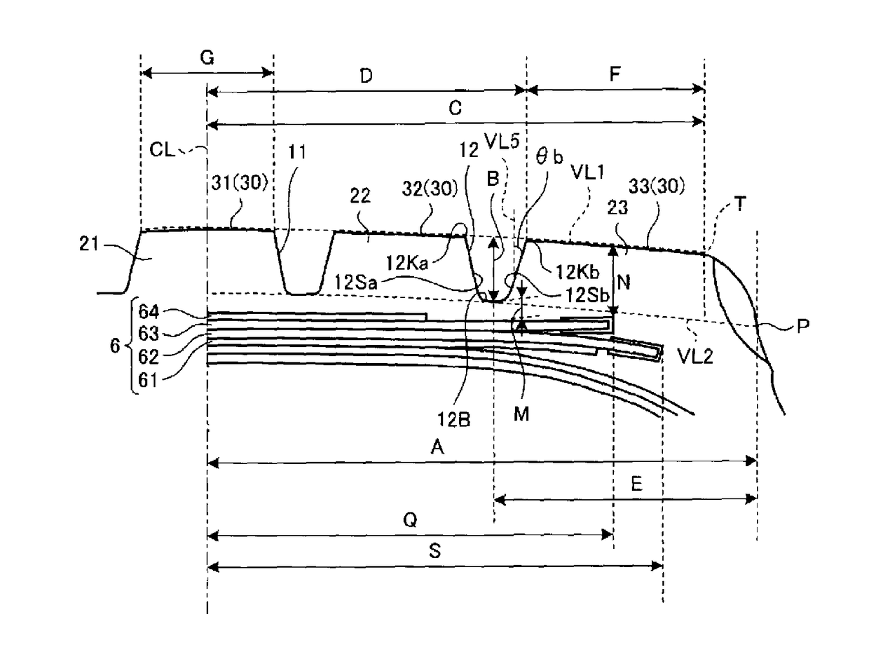
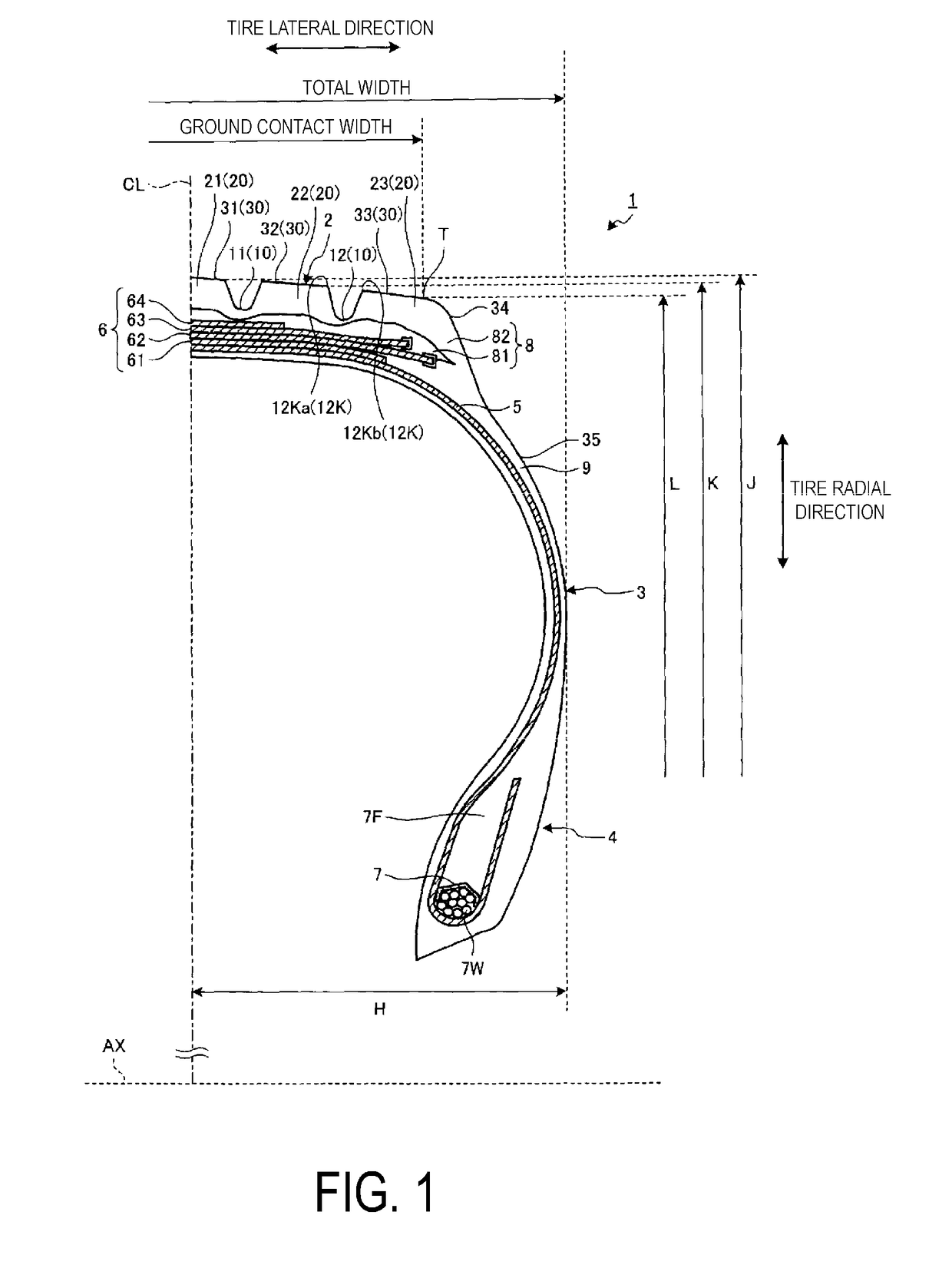
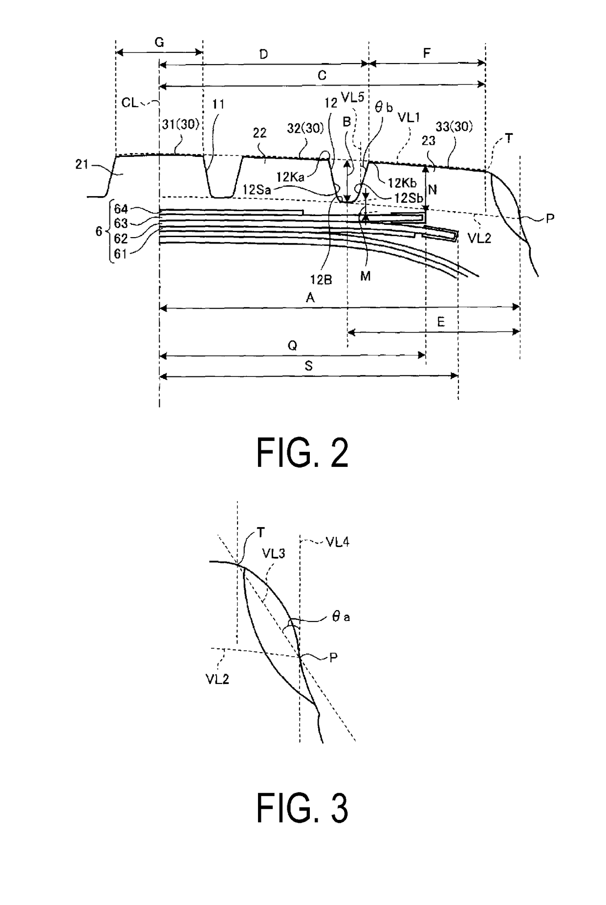
A pneumatic tire is provided with a tread portion and side portions. The tread portion includes shoulder main grooves and shoulder land portions. The following are defined in a meridian cross section of the tread portion: a first imaginary line passing through a ground contact surface, a second imaginary line passing through a bottom portion of a shoulder main groove and parallel to the first imaginary line, an intersection point between the second imaginary line and a surface of a shoulder land portion, and a tire equatorial plane. Given A as a distance in the tire lateral direction between the intersection point and the tire equatorial plane, B as a groove depth of the shoulder main groove, and C as a distance in the tire lateral direction between the tire equatorial plane and the ground contact edge, the condition 0.80≤(B+C) / A≤1.15 is satisfied.

Description

TECHNICAL FIELD[0001]The present technology relates to a pneumatic tire.BACKGROUND ART[0002]In a pneumatic tire, a tread pattern that includes grooves and land portions defined by the grooves is formed. The tread pattern is formed in a tread rubber. The grooves of the tread pattern include a circumferential main groove that extends in a tire circumferential direction, and a lug groove that at least partially extends in a tire lateral direction. A land portion defined by a plurality of the circumferential main grooves is called a rib or a block row. A rib is a continuous land portion not divided by a lug groove. A block row is a discontinuous land portion divided by a lug groove.[0003]In a heavy duty pneumatic tire mounted on a truck or a bus, the performance of the pneumatic tire can be improved by defining a groove depth of a shoulder rib groove and the like (refer to Japanese Unexamined Patent Publication No. 02-270608).[0004]When a heavy duty pneumatic tire swivels or runs onto a...

Claims


Application Information

Patent Timeline
Patent Type & Authority Applications(United States)
IPC IPC(8): B60C11/01B60C9/20B60C11/00
CPCB60C11/01B60C9/20B60C11/0008B60C2011/0025B60C2200/06B60C2011/013B60C2011/0355B60C2011/0016B60C2009/2019B60C2009/2022B60C2009/2064B60C2011/0033B60C9/28B60C11/005B60C3/04B60C2009/2083B60C2011/039Y02T10/86
Inventor YASUDA, RYUJI
Owner THE YOKOHAMA RUBBER CO LTD
Learn More