An improved airship

a technology of airships and airframes, applied in the direction of rigid airships, lighter-than-air aircraft, aircrafts, etc., can solve the problems of frequent accidents, difficult air and ground manoeuvre, and airships that cannot compete with modern heavier-than-air craft, so as to reduce both skin and form drag, reduce overall power, and save energy

Inactive Publication Date: 2018-10-04
BETTS CHRISTOPHER
View PDF9 Cites 1 Cited by
  • Summary
  • Abstract
  • Description
  • Claims
  • Application Information

AI Technical Summary

Benefits of technology

[0024]In a first aspect of embodiments described herein there is provided a lighter-than-air vehicle built in the shape of an annular aerofoil, the cross section having a rounded leading edge and relatively sharp trailing edge. Within the central duct of this aerofoil is placed an optimised propulsion system, which may take advantage of either or both of the increased airflow, and the ‘ducted fan’ topology of the overall shape of the airship envelope. The central location of the engine has both structural and safety advantages. Further, the outlet airflow can be controlled to create ‘vectored thrust’ to manoeuvre the airship, optionally in conjunction with other control surfaces.
[0044]Throughout the specification, the word ‘aerofoil’ refers to a ‘low drag object with a design which will seek to minimise drag and / or a smooth shape that encourages laminar air flow and / or reduces turbulence. An example of an aerofoil, without limitation includes an object which will have features like a rounded leading edge and a tapered trailing edge, and will have relatively smooth curves to minimise drag.

Problems solved by technology

Despite their early promise, airships have not been able to compete with modern heavier-than-air craft, outside niche industries such as tourism.
The energy cost of moving a large body through the air makes them uneconomic for cargo transport, while the large mass and relatively poor power (relative to their size) makes them difficult to manoeuvre both in the air and on the ground, leading to frequent accidents.
Finally their large size and limited weight carrying capacity led historically to a relatively flimsy construction that left them very vulnerable to wind and storm damage.
Further, their large size, which in most respects is a drawback, makes them ideal for running on solar power.
However the weight of the ring, the power requirements of the vehicle, and the difficulty in manoeuvring the structure meant that despite their initial promise, they proved impractical compared to helicopters for VTOL heavier-than-air flight.
But a succession of “Venturi tubes”, rather than having lower air resistance than a straight tube, in fact will have higher air resistance, and the numerous counter-rotating propellers will likewise be considered very inefficient.
Overall the thin central tube would be impractical, have very high air resistance, and would need to be very strong to support sufficient thrust to move the airship.
Further, the ‘adjustable tube’ aft would be relatively difficult and weighty to construct, while the forward inlet tube would have little effect, as one cannot steer by suction.
However the overall aerodynamics of the ‘high speed airship” are not optimised.
However, similarly to Jordan ('786) and Gembe ('411), there is no attempt at overall aerodynamic efficiency, and the non-streamlined shape of these ducts would make driving air through them very inefficient.
In general, placing engines in long thin ducts is not considered efficient.
However, despite Campbell's efforts to minimise drag, his sphere is intrinsically a high-drag shape, with significant turbulent flow (and accompanying drag) inevitable.
In many aspects the design is considered impractical as there is no consideration of airflow separation or the changes in overall shape required for different operational regimes.
Drucker discloses generating energy from the craft by floating with the wind, but such a mechanism is not possible, as an unpowered airship will float at the same speed as the wind, and there will be no differential airflow.
It is not considered practical to construct.
A number of inventions have attempted to reduce the drag by active airflow control to maintain laminar airflow for longer, and to remove the risk of airflow separation; e.g. by sucking air in at the rear of the vehicle, but there are significant practical difficulties in trying to do this in a traditional airship as it may require a great deal of tubing and pumps.
An underlying difficulty with all these systems is that the weight of the ducts, pipes and particularly the powerful engines required, make such systems very difficult to build in practical airships.
As the floating wind turbine is tethered, streamlining of the shroud is far less important than the ability to funnel air into the central blades, and despite the efforts of streamlining, the squat funnel shape of the shroud is likely to have significant turbulent drag behind it.

Method used


Image

  • An improved airship
  • An improved airship
  • An improved airship

Examples


first embodiment

[0109

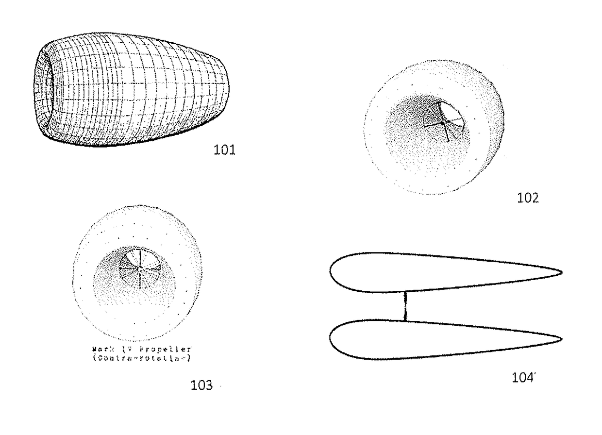
[0110]The first embodiment of my invention concerns a streamlined airship with a large central duct, shaped in the form of an annular aerofoil to minimise overall drag.

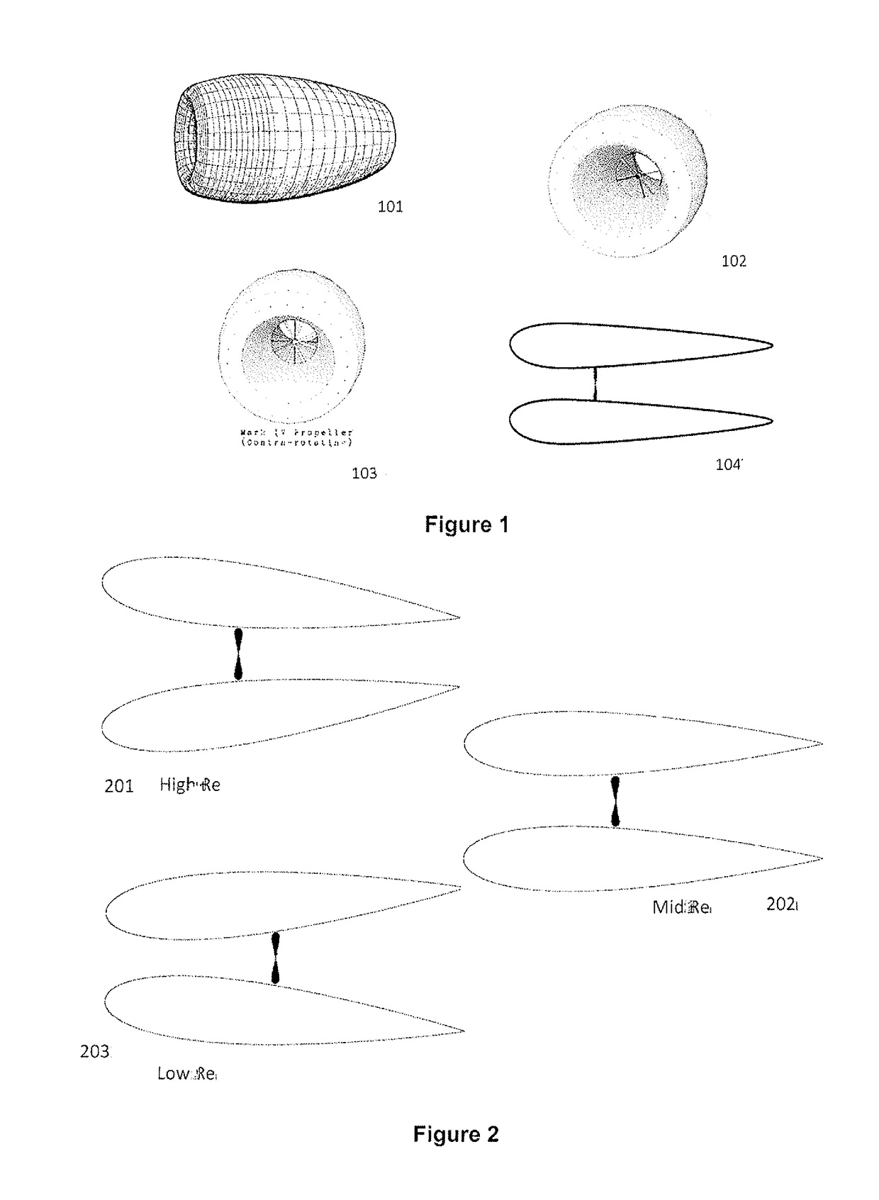
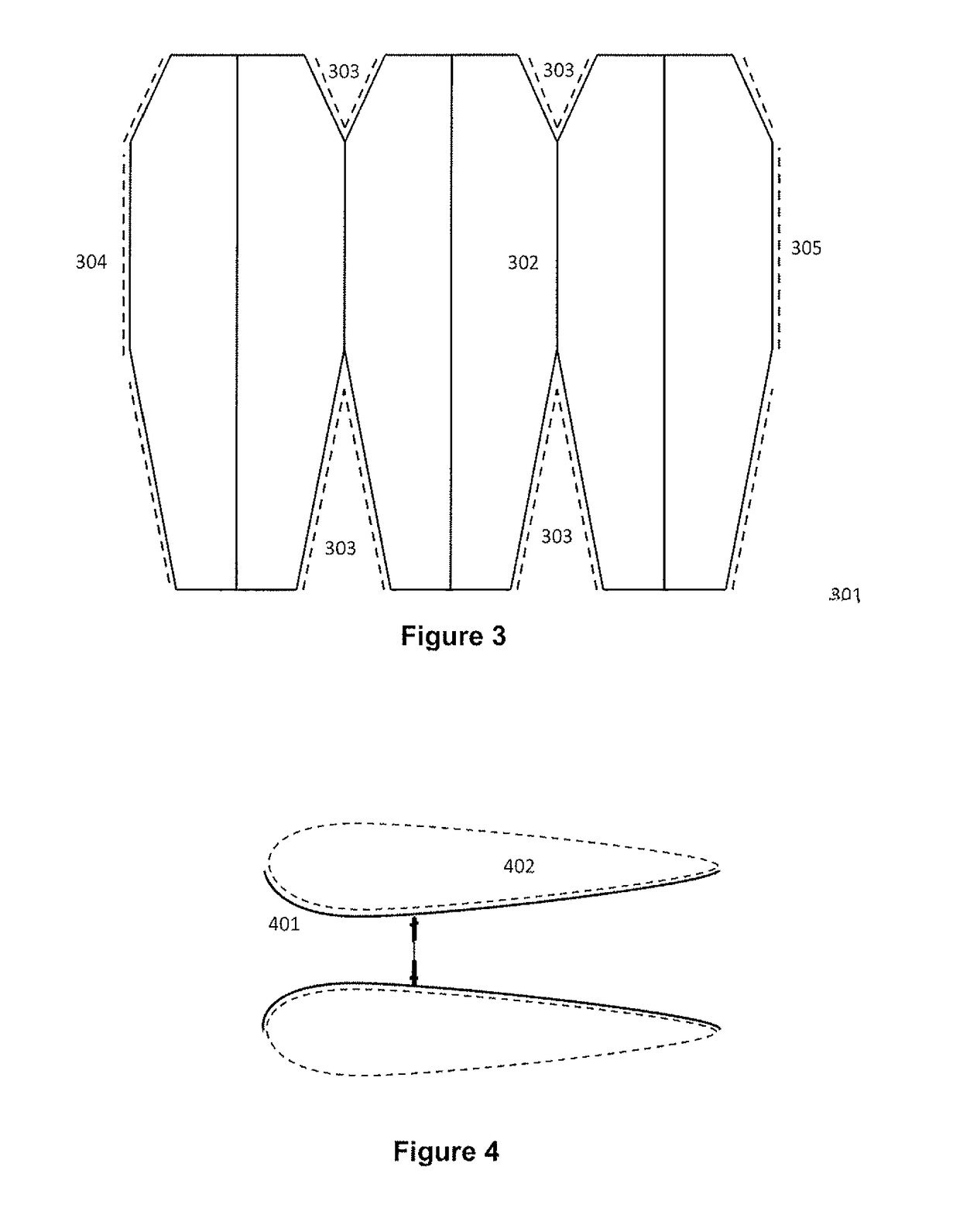
[0111]FIG. 104. is a side view illustrating the general shape in cross section. The ‘sides’ of the airship are chosen to have the streamlined cross section of an aerofoil.

[0112]Within the duct is an engine, such as a propeller. A propeller has many advantages in this configuration, as it may operate more efficiently due to the reduced tip turbulence from operating within a ‘shroud’, and benefit from the increased airflow of the large forward opening. Additionally, as airships generally operate at lower speeds than aircraft, a larger, slower, but more efficient propeller may be used, and may be designed to provide thrust along its entire length (as opposed to traditional propellers which ‘flatten out’ near their tips to reduce turbulence).

[0113]Finally, the front of the airship will concentrate air into the centra...


PUM


Abstract

An airship in the shape of an annular aerofoil, designed so that the sides of the airship have a streamlined shape. Within the central passage is an efficient propulsion unit, the thrust from which is vectored to provide manoeuvrability.

Description

FIELD OF INVENTION[0001]The present invention relates to lighter-than-air vehicles in general.[0002]In one form, the invention relates to a lifting device, such as an airship in the shape of an annular aerofoil with accompanying structural, propulsive and aerodynamic features to enhance such a device for relatively higher speed operation, better manoeuvrability, and safe operation.[0003]In one particular aspect the present invention is suitable for use as a relatively small ‘drone’ aircraft.[0004]It will be convenient to hereinafter describe the invention in relation to an airship, however it should be appreciated that the present invention is not limited to that use only.BACKGROUND ART[0005]Throughout this specification the use of the word “inventor” in singular form may be taken as reference to one (singular) inventor or more than one (plural) inventor of the present invention.[0006]It is to be appreciated that any discussion of documents, devices, acts or knowledge in this specif...

Claims


Application Information

Patent Timeline
Patent Type & Authority Applications(United States)
IPC IPC(8): B64B1/14B64B1/26B64B1/36B64B1/38
CPCB64B1/14B64B1/26B64B1/36B64B1/38B64B1/70B64B1/00B64B1/06
Inventor BETTS, CHRISTOPHER
Owner BETTS CHRISTOPHER
Why Eureka
Try Eureka