Rolled-thread bolt production method

a production method and technology of thread bolts, applied in heat treatment furnaces, heat treatment equipment, furnaces, etc., can solve the problems of large-scale lubrication facilities, easy damage to thread parts, and long treatment time, and achieve the effect of increasing the coefficient of friction

Inactive Publication Date: 2018-10-04
TOYOTA JIDOSHA KK
View PDF4 Cites 0 Cited by
  • Summary
  • Abstract
  • Description
  • Claims
  • Application Information

AI Technical Summary

Benefits of technology

[0014]With the rolled-thread bolt production method according to the above aspect, it is possible to increase the coefficient of friction at the time of tightening of the rolled-thread bolt.

Problems solved by technology

JP 2004-232757 A points out that, with the rerated art, the threaded-portion is easily damaged because the shot blasting is performed after the thread rolling.
Note that phosphate lubrication coating, which has been employed for cold forging and the like for many years, requires a large-scale lubrication facility, requires a long treatment time, and produces sludge and waste fluid that place heavy burdens on the environment.
Further, the single-liquid lubricant can be easily washed away by water or the like.

Method used


Image

  • Rolled-thread bolt production method
  • Rolled-thread bolt production method
  • Rolled-thread bolt production method

Examples


Embodiment Construction

[0019]Hereinafter, example embodiments of the disclosure will be described in detail with reference to the accompanying drawings. While a bolt with a washer, which is used in a vehicle, will be described below as a rolled-thread bolt, the bolt is just an example for description and may be used for various purposes other than the use in a vehicle. A rolled-thread bolt without a washer or a rolled-thread bolt without a head may be adopted. The shapes, dimensions, materials, and so forth described below are just examples for description, and may be changed as appropriate in accordance with the specifications of a rolled-thread bolt. The same elements will be denoted by the same reference symbols in all the drawings, and description thereof will not be repeated.

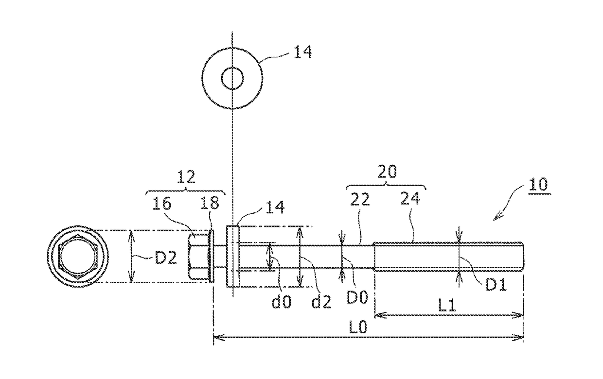
[0020]FIG. 1 is a view of a rolled-thread bolt 10. An overall view of the rolled-thread bolt 10 is illustrated in the right-side region in FIG. 1. A view of the rolled-thread bolt 10 as seen from the head-side of the rolled-threa...


PUM

PropertyMeasurementUnit
frictional coefficientaaaaaaaaaa
shapeaaaaaaaaaa
frictional coefficientaaaaaaaaaa

Abstract

A rolled-thread bolt production method includes: forming a steel wire into a workpiece having a prescribed unthreaded-bolt shape; forming a threaded-portion on the workpiece through thread rolling; and performing shot blasting on an entire surface of the workpiece after forming the threaded-portion.

Description

INCORPORATION BY REFERENCE[0001]The disclosure of Japanese Patent Application No. 2017-064490 filed on Mar. 29, 2017 including the specification, drawings and abstract is incorporated herein by reference in its entirety.BACKGROUND1. Technical Field[0002]The disclosure relates to a rolled-thread bolt production method.2. Description of Related Art[0003]In order to produce a rolled-thread bolt, a steel wire that has been wound into a coil form is cut into pieces having a prescribed length, and then each piece is subjected to cold heading to be formed into an unthreaded bolt including a head having a prescribed shape and a stem that is integral with one end of the head. Then, a threaded-portion is formed, through thread rolling, in a distal-end-side region of the stem.[0004]The related art section of Japanese Unexamined Patent Application Publication No. 2004-232757 (JP 2004-232757 A) refers to a technique in which shot blasting is performed after thread rolling and before a thermal tr...

Claims


Application Information

Patent Timeline
Patent Type & Authority Applications(United States)
IPC IPC(8): F16B33/06B21K1/50B21H3/02C21D7/06
CPCF16B33/06B21K1/50B21H3/02C21D7/06B21F45/16C21D9/0093C21D1/25B21F5/005B21K1/46
Inventor TAKEUCHI, TAKETO
Owner TOYOTA JIDOSHA KK
Why Eureka
Try Eureka