Vehicle-mounted camera calibration system

a technology of vehicle-mounted cameras and calibration systems, which is applied in the field of vehicle-mounted camera calibration systems, can solve the problems of requiring time and labor for further processing

Inactive Publication Date: 2018-10-04
PANASONIC INTELLECTUAL PROPERTY MANAGEMENT CO LTD
View PDF2 Cites 15 Cited by
  • Summary
  • Abstract
  • Description
  • Claims
  • Application Information

AI Technical Summary

Benefits of technology

[0014]According to the present disclosure, it is possible to calibrate the camera images automatically during a transfer of the vehicle on the assembly line without stopping each of vehicles on an assembly line of the vehicles. In other words, the images to be displayed on the vehicle-mounted display can be calibrated with no need to position each of the vehicles.

Problems solved by technology

In such a case, the calibrating target should be accurately placed each time, which further requires time and labor.

Method used


Image

  • Vehicle-mounted camera calibration system
  • Vehicle-mounted camera calibration system
  • Vehicle-mounted camera calibration system

Examples


first exemplary embodiment

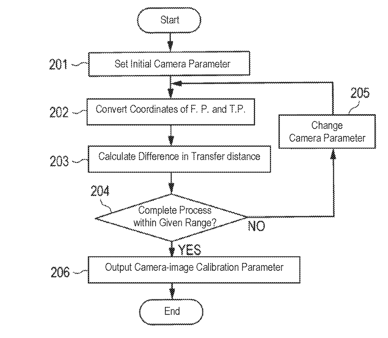
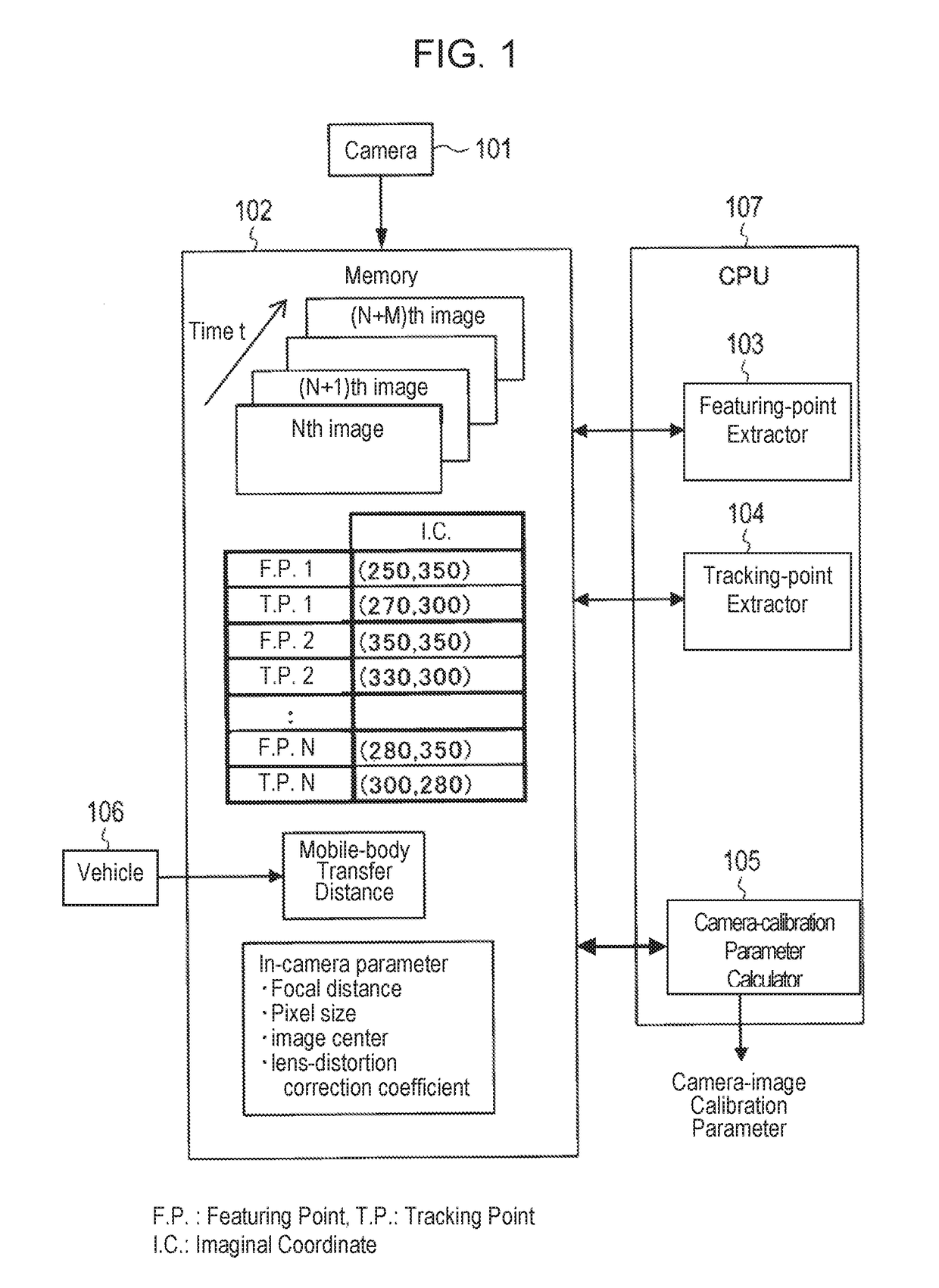
[0028]Exemplary embodiments of the present disclosure will be detailed hereinafter with reference to the accompanying drawings. FIG. 1 is a block diagram showing the functional structure of the camera calibrating device in accordance with a first exemplary embodiment of the present disclosure. The structure and the operation of the camera calibrating device in accordance with the first exemplary embodiment are demonstrated hereinafter.

[0029]The camera calibrating device in accordance with the present exemplary embodiment is mounted to a mobile body such as a vehicle. This device is expected to calibrate images shot with camera 101, and includes memory 102, featuring-point extractor 103, tracking-point extractor 104, and camera-calibration parameter calculator 105. FIG. 1 also shows vehicle 106.

[0030]When CPU (central processing unit) 107 of the camera calibrating device executes a program stored in a ROM (read only memory, not shown), thereby featuring-point extractor 103, tracking-...

second exemplary embodiment

[0057]The present disclosure is not limited only to the first exemplary embodiment discussed above, but an embodiment partially modified is applicable to the present disclosure. A second exemplary embodiment of the present disclosure is detailed hereinafter with reference to the accompanying drawings.

[0058]FIG. 9 is a block diagram showing a functional structure of a camera calibrating device in accordance with the second exemplary embodiment. In the camera calibrating device shown in FIG. 9, structural elements similar to those in the camera calibrating device shown in FIG. 1 have the same reference marks, and the description thereof are omitted here. The camera calibrating device shown in FIG. 9 differs from that shown in FIG. 1 in the presence of mobile-body transfer-distance calculator 806 that is added in CPU 107.

[0059]Mobile-body transfer-distance calculator 806 calculates a transfer distance of a mobile body (vehicle). The process done in mobile-body transfer-distance calcula...


PUM


Abstract

A vehicle-mounted camera calibration system is provided. This system automatically calibrates camera images during the transfer of vehicles on an assembly line of the vehicles without stopping the vehicles on the assembly line. This system includes a camera mounted to each one of the vehicles for sequentially shooting an image of a road surface, a memory for chronologically storing the images shot with the camera, a featuring-point extractor for extracting a featuring point from each of the shot images stored in the memory, a tracking-point extractor for extracting a tracking point that represents a position to which the featuring point has been transferred after a lapse of a given time, and a camera-calibration parameter calculator for calculating a calibration parameter to be used for calibrating images shot by the camera, from the featuring point and the tracking point.

Description

CROSS-REFERENCE TO RELATED APPLICATIONS[0001]This application is a continuation of the PCT International Application No. PCT / JP2017 / 002092 filed on Jan. 23, 2017, which claims the benefit of foreign priority of Japanese patent application No. 2016-019072 filed on Feb. 3, 2016, the contents all of which are incorporated herein by reference.BACKGROUND1. Technical Field[0002]The present disclosure relates to a vehicle-mounted camera calibration system that uses an image shot with a camera for calibrating an image to be displayed on a vehicle-mounted monitor. Hereinafter, the image to be displayed on a vehicle-mounted monitor is referred as a camera image.2. Description of the Related Art[0003]Conventionally, an image, shot with a vehicle-mounted camera, behind the vehicle is displayed on a vehicle-mounted monitor for a driver to recognize a blind spot, viz. a situation right behind the vehicle. This kind of displaying the image improves visibility by a driver when the driver reverses t...

Claims


Application Information

Patent Timeline
Patent Type & Authority Applications(United States)
IPC IPC(8): G06T7/80G06T7/246B60R11/04
CPCG06T7/80G06T7/246B60R11/04G06T2207/30252H04N7/183B60R2300/402H04N17/002H04N23/60H04N25/61
Inventor KIMOTO, DAISUKEMATO, RYUICHI
Owner PANASONIC INTELLECTUAL PROPERTY MANAGEMENT CO LTD
Why Eureka
Try Eureka