Inline method for producing a spring strip profile for a slatted frame

a technology of slatted frame and spring strip, which is applied in the direction of seating furniture, mattresses, coatings, etc., can solve the problems of glass fiber reinforced core rod winding that requires considerable force and is no longer possible, and the core profile bar is under high,

Active Publication Date: 2018-10-11
OKE GROUP
View PDF6 Cites 4 Cited by
  • Summary
  • Abstract
  • Description
  • Claims
  • Application Information

AI Technical Summary

Benefits of technology

[0004]The problem addressed by the present invention is, therefore, to improve an inline method for producing a spring profile strip for forming a slatted frame such that, in particular, a significantly higher throughput speed is achieved with the inline method and furthermore to effect a more economical manufacturing method.

Problems solved by technology

The winding of a glass fiber-reinforced core rod requires considerable forces and is no longer possible beginning at a certain cross-sectional diameter of the core rod.
Also, the later use of the tensioned winding roll in the extrusion line poses safety risks should the core profile bar that is under high bending stress break.
However, particularly the necessary interim storage of the prefabricated core profile bar on rolls leads to a significant loss of time, which entails economic disadvantages in the production of the spring strip.
The disadvantage of this known inline method for producing a spring strip profile is that the throughput speed through the pultrusion process is very slow, i.e., the theoretically possible throughput speeds in the downstream extrusion cannot be utilized, because a certain residence time of the glass-fiber bundle impregnated with a reaction resin in the pultrusion tool is required to effect sufficient curing.
If curing has not progressed sufficiently, the cross-section of the core profile bar is changed by the pressure of the thermoplastic melt or the structure of the core profile is even destroyed during the subsequent extrusion.
A higher heat input per unit of time can also not be achieved with the known method by arbitrarily extending the heated pultrusion tool because the frictional forces in the tool would then no longer be handled with a reasonable expenditure.

Method used


Image

  • Inline method for producing a spring strip profile for a slatted frame
  • Inline method for producing a spring strip profile for a slatted frame
  • Inline method for producing a spring strip profile for a slatted frame

Examples


Embodiment Construction

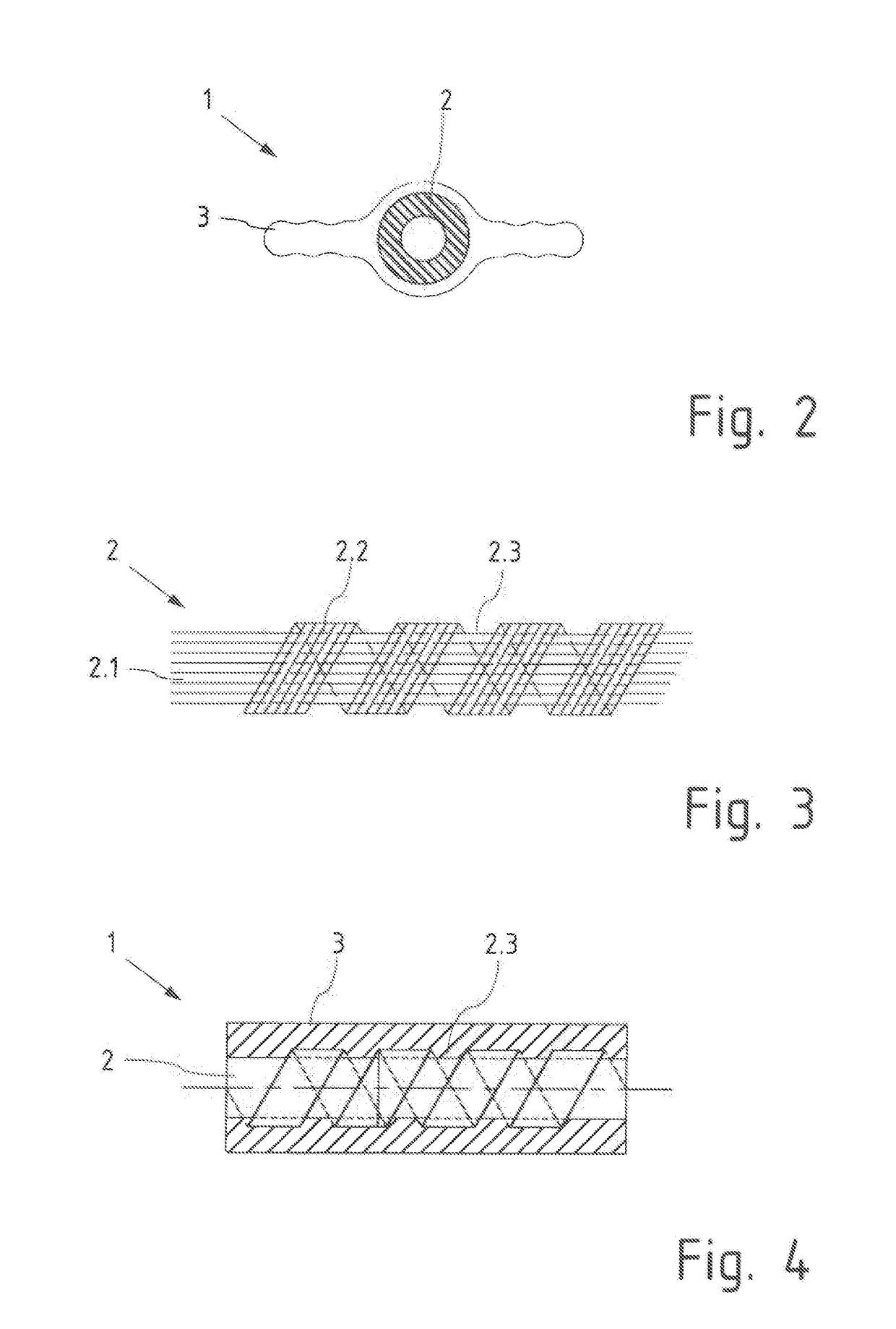
[0025]The preferred embodiments of the present invention will now be described with reference to FIGS. 1-4 of the drawings. Identical elements in the various figures are designated with the same reference numerals.

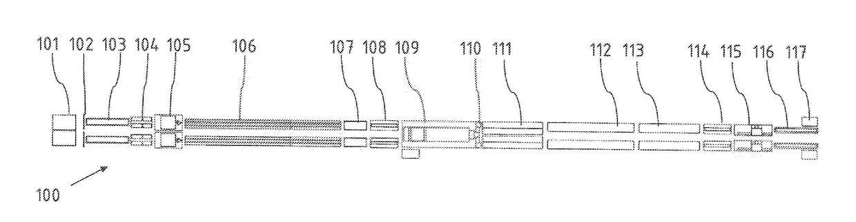
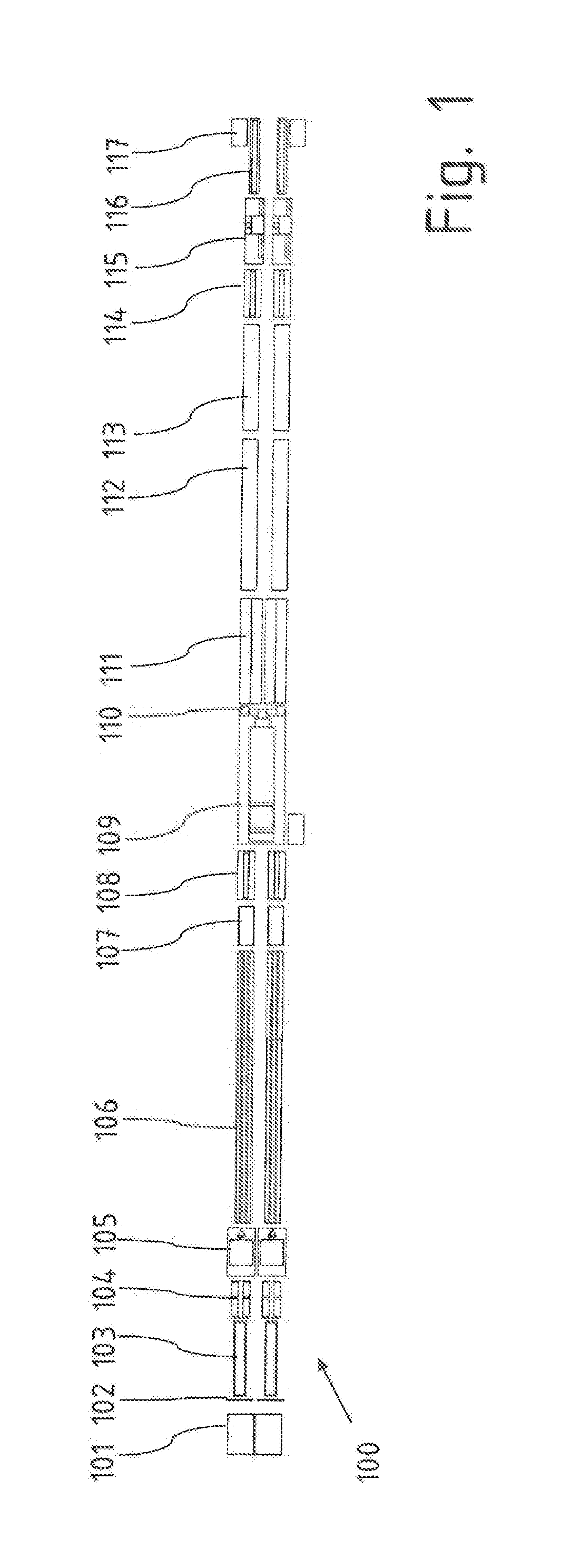
[0026]The method according to the invention is explained below with reference to the production system 100 shown in a schematic block view from above in FIG. 1, in which the production direction runs from left to right.

[0027]In the exemplary embodiment, the schematically illustrated production system 100 is designed as a duo production system, i.e., two almost identical production lines run parallel next to each other, wherein in the illustrated embodiment, most components, except for an extruder 109, are present separately for each line, that is, double. The entire length of the production line from beginning to end is 40 m in the example shown.

[0028]Multiple bobbins are kept ready on a creel 101 so that fibers or threads or filaments wound thereon from a plurality of ind...


PUM

PropertyMeasurementUnit
temperature resistantaaaaaaaaaa
lengthaaaaaaaaaa
take-off speedaaaaaaaaaa

Abstract

An inline method for producing a spring strip profile (1) for a slatted frame that comprises at least one core strand (2) formed by a fiber-reinforced plastic and at least one thermoplastic cover layer (3) surrounding the core strand (2), comprises at least the following steps: joining multiple fibers, threads and / or filaments to form a fiber bundle (2.1); impregnating the fiber bundle (2.1) with a thermally activatable reaction resin; molding the outer contour of the fiber bundle (2.1) impregnated with the reaction resin; thermally activating the reaction resin (2.1) to form a cured core strand; introducing the core strand (2) into an extruder head (110); applying thermoplastic melt in the extruder head (110) to form the cover layer (3) on the spring strip profile (1); and cooling and calibrating the spring strip profile (1) in a cooling and calibrating device (111, 112, 113). The outer contour of the fiber bundle (2.1) is wrapped around, in a winding machine (105), by at least one thread or filament (2.2) supplied laterally in relation to the fiber bundle in at least one position and orientation, and, in a heating section (106), before the core strand (2) is introduced into the extruder head (110), at least a partial curing of the reaction resin is achieved, at least in the wrapped outer layer of the fiber bundle (2.1).

Description

BACKGROUND OF THE INVENTION[0001]The invention relates to an inline method for producing a spring strip profile for a slatted frame which comprises at least one core strand formed by a fiber-reinforced plastic and at least one thermoplastic cover layer surrounding the core strand. The method comprises at least the following steps: joining multiple fibers, threads and / or filaments to form a fiber bundle; impregnating the fiber bundle with a thermally activatable reaction resin; molding the outer contour of the fiber bundle impregnated with the reaction resin; thermally activating the reaction resin to form a cured core strand; introducing the core strand into an extruder head; applying thermoplastic melt in the extruder head to form the cover layer on the spring strip profile; and cooling and calibrating the spring strip profile in a cooling and calibrating device.[0002]EP 2 865 296 A1 shows various profile shapes for a spring strip profile, which comprises a core strand made of a fi...

Claims


Application Information

Patent Timeline
Patent Type & Authority Applications(United States)
IPC IPC(8): A47C23/06B29C47/02B29C47/28B29C47/78B29C70/52B29C48/06B29C48/34B29C48/90
CPCA47C23/061B29C47/025B29C47/027B29C47/28B29C47/782B29C70/521B29C35/02B29C47/0016B29C47/003B29C47/1036B29C53/60B29C48/34B29C48/79B29C48/154B29C48/156B29C48/06B29C48/12B29C48/2883B29C53/56B29C70/22
Inventor WESTING, KERSTINBARTEL, ANDREASPLAGEMANN, FLORIAN
Owner OKE GROUP
Why Eureka
Try Eureka