These valves have been tested extensively for replacement of aortic, mitral, and pulmonic valves, but replacement of tricuspid valves remains challenging given the complex and delicate
anatomy to which prostheses must attach.
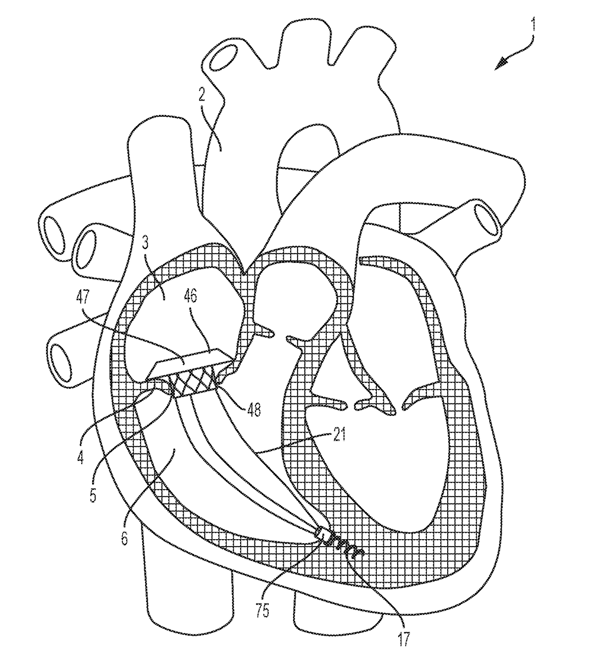
Anchoring transcatheter valves, in general, or transcatheter tricuspid valves, in particular, remains difficult, because doing so, either in the in-situ position of cardiac valves, or in other body lumens, requires interaction with a great variety of shapes and sizes of either cardiac valve annuli or other lumens.
Several groups have described intracardiac anchors and tethers, but these systems have limitations in their applications.
The need to access the heart via the chest might increase the risk of the procedure in patients with a decreased pumping function (
ejection fraction), or in patients with fragile tissues, particularly in applications involving the
tricuspid valve.
Finally, there is a proximal anchoring feature to fix the proximal end of the coaptation
catheter subcutaneously adjacent the subclavian
vein.” The first limitation of this application is the inability to retrieve and reposition the anchor in the case of a wrong site or sub-
optimal deployment.
The next limitation is that the anchor rail is fixed to the anchor.
The proximal anchor rail is connected to a subcutaneous pocket, and all of this brings the attendant risks of permanent venous leads, specifically
thrombosis, infection, and venous
stenosis.
Despite some of the advantages of Solem's application, this application also suffers limitations.
. . ” It is doubtful, however, that the tissue-engaging, backward-bending prongs can be retrieved easily in this fashion without damaging tissue in the process, and a more safely retrievable anchor is desired.
Further, the prongs might be safe in one location of the heart, but might cause damage (i.e. perforation) if they need to be moved to a different location, because the arm length is not adjustable.
Moreover, limiting paravalvular regurgitation of transcatheter mitral and tricuspid valves is challenging because the mitral and tricuspid annuli are complex
saddle-shaped structures that are highly dynamic during the
cardiac cycle.
In patients receiving
transcatheter aortic valve replacements (TAVR), investigators have developed technologies to mitigate paravalvular regurgitation, but these approaches have limitations, especially in the presence of intracardiac leads.
For transcatheter tricuspid valves, direct
apposition of the valve frame to the tricuspid annulus might not be desirable or feasible because unlike the aortic annulus, the tricuspid annulus is distensible, with minimal external support, and prone to injury.
Additionally, sealing an intracardiac lead by
trapping it between the valve frame and annulus would increase the risk of injury to the lead, which is undesirable.
Three TMVR devices—
Caisson, HighLife, and MValve—use an annular anchor as a docking
system for the TMVR device, which would squeeze, and likely damage, any intracardiac lead between the anchor and the TMVR device.
Constraining this freedom might contribute to left ventricular dysfunction.
Thus, in order to limit paravalvular regurgitation, current TMVR devices must anchor and constrain the
mitral annulus, and this could have deleterious effects on left
ventricular function.
The Neovasc Tiara atrial skirt suffers the biggest limitation by being asymmetrical to conform to the “D-shaped”
mitral annulus and to the aorto-mitral curtain.
The skirts of the other TMVRs are symmetrical and are potentially compatible with the
right atrial floor and tricuspid annulus, but these skirts lack the downward force and flexibility (along the perpendicular axis of the annulus) that are required for either reduction of paravalvular regurgitation or for sealing of intracardiac leads.
Although Abbott Vascular Tendyne valve avoids annular anchoring by using an epicardial valve tether, its skirt also lacks the force and flexibility to seal around an intracardiac lead.
These funnel-shaped skirts easily flex inwards and do not have any mechanism to increase outward and downward force of the atrial skirt differentially.
Finally, another limitation of current atrial skirts is their fixation to their associated TMVR devices.

