Optical cable for terrestrial networks

a terrestrial network and optical cable technology, applied in the field of optical cables, can solve the problems of increasing the overall cross-sectional increasing the load required to install, and reducing the installation length of the cable, so as to reduce the minimum bend diameter of the cable, improve tensile strength, and reduce the size

Active Publication Date: 2018-10-11
PRYSMIAN SPA
View PDF7 Cites 2 Cited by
  • Summary
  • Abstract
  • Description
  • Claims
  • Application Information

AI Technical Summary

Benefits of technology

[0013]Further, as known, the stiffness of the strength member and the cable weight influence the loads required to install the cable and hence the installation length. Typically, given a maximum tensile strength, the larger the cable, the heavier the cable and the shorter the installation length. Moreover, the stiffer the cable, the greater the load required to install it (in particular, if the cable route comprises a corner). Therefore, the presence of the central strength member disadvantageously reduces the installation length of the cable.
[0018]Further, as far as the cable of EP 0 256 704 is concerned, the alleged advantage of this cable construction is improved tensile strength. However, this cable exhibits other disadvantages such as a relatively large cable size and a high bend resistance.
[0020]In particular, the Applicant has tackled the problem of providing an optical cable for terrestrial networks comprising an optical module, which allows providing cables with a reduced size and an improved tensile strength with respect to known cables, and which, at the same time, allows reducing the minimum bend diameter of the cable and allows providing a longer installation length.
[0021]The Applicant found that the above problem is solved by an optical cable comprising an optical module with a strength member, a number of optical fibers stranded around the strength member and a retaining element surrounding the optical fibers. The optical cable of the invention advantageously has a reduced diameter in comparison to known cables comprising a same number of optical fibers. This allows designing compact cables for FTTX applications. In particular, the optical cable of the invention may not need any central strength member since the tensile strength is conferred to the cable by the optical modules, in particular by the strength members thereof. The fact that the cable according to the present invention does not need any central strength member provides a reduced minimum bend diameter and a longer cable installation length.
[0023]Furthermore, the optical module of the optical cable of the invention may be manufactured in an easy and economically effective way.

Problems solved by technology

First of all, the presence of the central strength member disadvantageously increases the overall cross-sectional diameter of the cable.
Moreover, the stiffer the cable, the greater the load required to install it (in particular, if the cable route comprises a corner).
Therefore, the presence of the central strength member disadvantageously reduces the installation length of the cable.
Furthermore, the buffering tubes of a MLT cable have little inherent stiffness or tensile strength, with the exception of that afforded by the fibers.
This may result in module damage.
All such bend management devices add costs to the system.

Method used


Image

  • Optical cable for terrestrial networks
  • Optical cable for terrestrial networks
  • Optical cable for terrestrial networks

Examples


Embodiment Construction

[0053]For the purpose of the present description and of the appended claims, except where otherwise indicated, all numbers expressing amounts, quantities, percentages, and so forth, are to be understood as being modified in all instances by the term “about”. Also, all ranges include any combination of the maximum and minimum points disclosed and include any intermediate ranges therein, which may or may not be specifically enumerated herein.

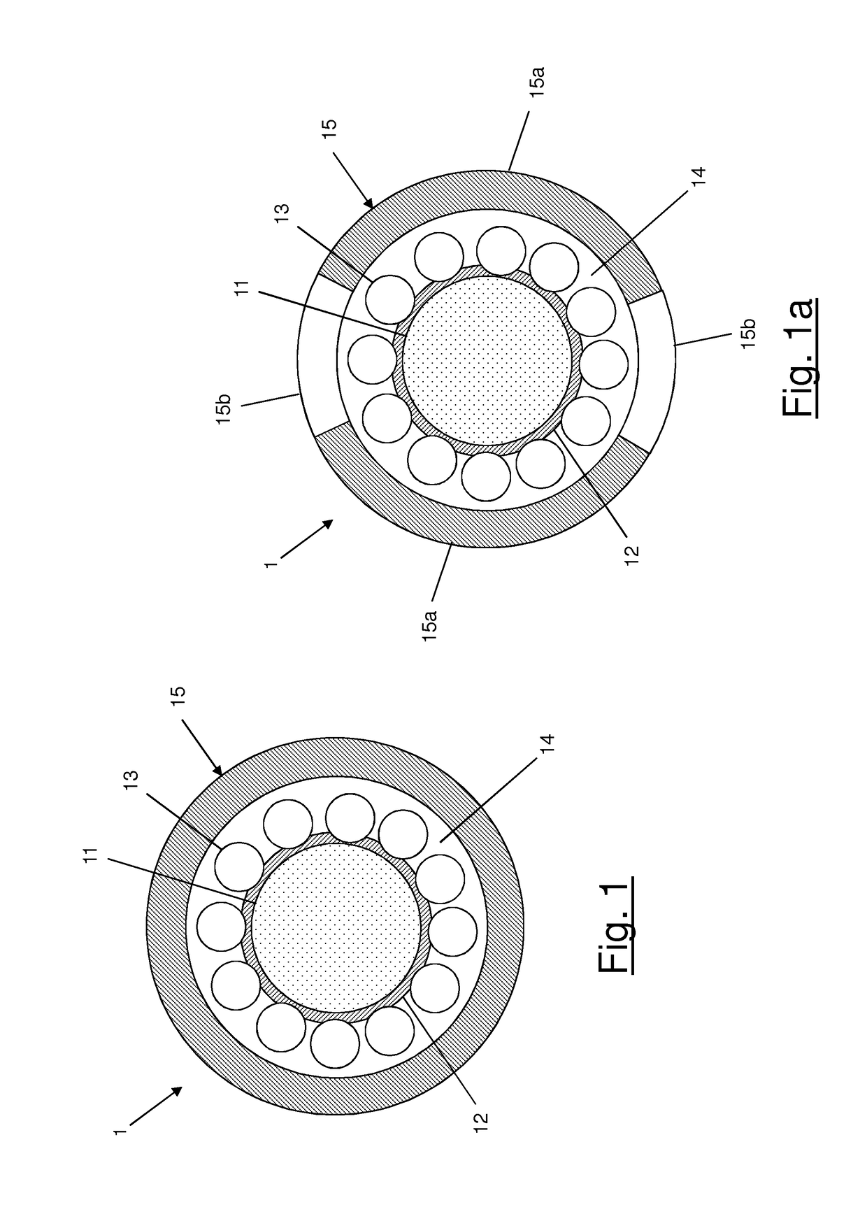
[0054]FIG. 1 shows an optical module 1 according to an embodiment of the present invention.

[0055]The optical module 1 comprises a strength member 11, optionally covered by a coating 12.

[0056]The strength member 11 is preferably in the form of a rod. Preferably, the rod is made of a glass reinforced plastic (GRP). More preferably, the rod is made of a GRP having a Young's modulus comprised between 25 MPa and 125 MPa. Even more preferably, the Young's modulus of the GRP is equal to 50 MPa. The strength member 11 has preferably a diameter which is co...


PUM


Abstract

An optical cable includes an optical module which includes a strength member, a plurality of optical fibers arranged about the strength member, the optical fibers being arranged substantially on a circumference concentric with the strength member, and a retaining element arranged about the plurality of optical fibers.

Description

TECHNICAL FIELD[0001]The present invention relates to the field of optical cables. More particularly, the present invention relates to an optical cable comprising an optical module, the cable being suitable for terrestrial networks, in particular—but not exclusively—optical access networks for FTTX applications (wherein FTTX means fiber to the X, where X can be home, cabinet, curb, or the like).BACKGROUND ART[0002]As known, an optical cable typically comprises an optical core and an external sheath enclosing the optical core. The external sheath is typically made of a polymeric material and has the primary function of protecting the optical core from the mechanical stresses.[0003]The optical core of these type of cables typically comprises one or more optical modules, the term “optical module” indicating a fiber bundle—comprising one or more optical fibers—and a retaining element (e.g. a buffer tube or a tape) surrounding the optical fibers. The retaining element carries out the fun...

Claims


Application Information

Patent Timeline
Patent Type & Authority Applications(United States)
IPC IPC(8): G02B6/44
CPCG02B6/4494G02B6/4486G02B6/441G02B6/4433G02B6/4434G02B6/4484G02B6/4431G02B6/443G02B6/44384
Inventor LANG, IAN DEWISPICER, LEE ANTHONYDAVIES, MARTIN VINCENT
Owner PRYSMIAN SPA
Why Eureka
Try Eureka