
Vehicle remote diagnosis method and device

Inactive Publication Date: 2018-10-11
LAUNCH TECH CO LTD
View PDF4 Cites 12 Cited by
  • Summary
  • Abstract
  • Description
  • Claims
  • Application Information

AI Technical Summary

Benefits of technology

The present patent application provides a method and device for remotely diagnosing and maintaining vehicles. It allows users to easily connect the diagnosis equipment to the vehicle, obtain real-time data, and analyze the vehicle's condition. The diagnosis equipment can also send instructions to the vehicle for remote maintenance, improving the efficiency and accuracy of diagnostic and maintenance operations. The technical effects include improved convenience, accuracy, and realization of remote diagnosis and maintenance of vehicles.

Problems solved by technology

A variety of fault conditions will occur inevitably to a vehicle during use.
This diagnosis method has a long diagnosis method and needs the technical staff to diagnose on site, and therefore the applicability is low.
The remote diagnosis has been realized by those methods, but there are also some drawbacks: every time the remote diagnosis need to be carried out, the connection operation of diagnosis equipments need to be performed, and therefore the vehicle cannot be detected and diagnosed at any time; moreover, performing these connection requires certain professional knowledge, which is inconvenient to the vehicle owner; in addition, the existing remote diagnosis mainly obtains the data of the vehicle remotely and in an unidirectional way, but cannot control and operate the vehicle, the diagnosis function is imperfect.

Method used


Image

  • Vehicle remote diagnosis method and device
  • Vehicle remote diagnosis method and device
  • Vehicle remote diagnosis method and device

Examples


first embodiment

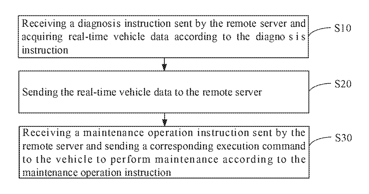
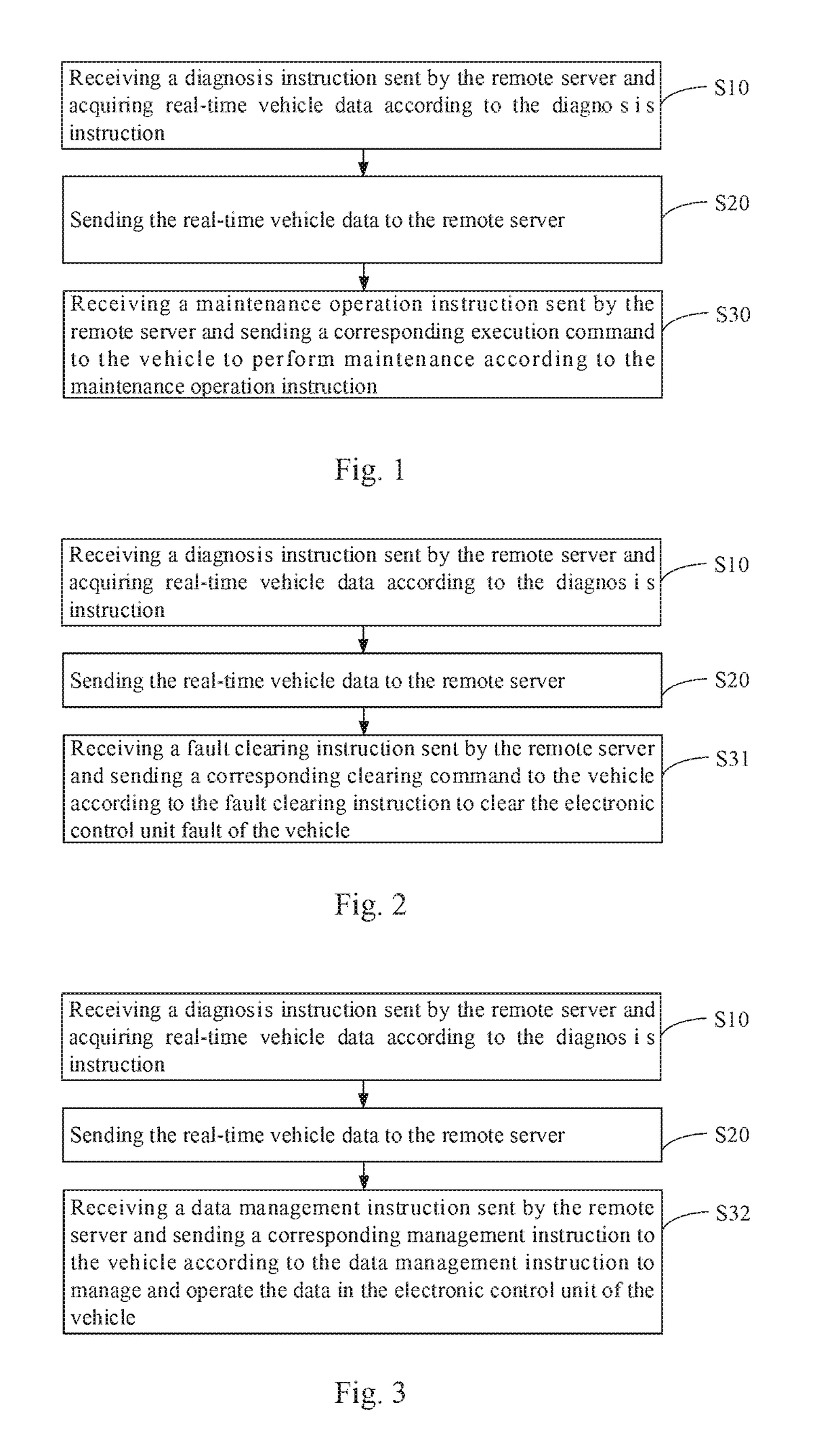
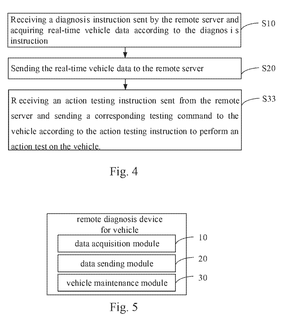
[0044]As shown in FIG. 1, FIG. 1 is a schematic flowchart of a vehicle remote diagnosis method according to the present application.

[0045]In this embodiment, the diagnosis method is applied to a vehicle diagnosis equipment which is placed on the vehicle as the on-board equipment, a remote communication connection with a remote server, the diagnosis method comprising the following steps:

[0046]Step S10, receiving a diagnosis instruction sent by the remote server and acquiring real-time vehicle data according to the diagnosis instruction;

[0047]In this embodiment, the vehicle remote diagnosis is performed by the vehicle diagnosis equipment. In the existing diagnosis method, when the diagnosis is required, the diagnosis cannot be performed until the professional diagnosis equipment is connected to the OBD connector of the vehicle, and the connection operation must be performed before each diagnosis. In this embodiment, a remote communication device is integrated in the professional diagn...

second embodiment

[0055]As shown in FIG. 2, FIG. 2 is a schematic flowchart of a vehicle remote diagnosis method according to the present application.

[0056]Based on the embodiment shown in FIG. 1 described above, Step S30 comprises:

[0057]Step S31, receiving a fault clearing instruction sent by the remote server and sending a corresponding clearing command to the vehicle according to the fault clearing instruction to clear the fault of the vehicle electronic control unit.

[0058]In this embodiment, the maintenance personnel can enter the fault clearing instruction when the maintenance personnel completes the analysis of the vehicle state through the remote server. The remote server will send the fault clearing instruction to the diagnosis equipment. The diagnosis equipment will sends the corresponding clearing command to the vehicle according to the fault clearing instruction to clear the fault of the vehicle electronic control unit when the diagnosis equipment receives the fault clearing instruction.

[0...

third embodiment

[0060]As shown in FIG. 3, FIG. 3 is a schematic flowchart of a vehicle remote diagnosis method according to the present application.

[0061]Based on the embodiment shown in FIG. 1 described above, Step S30 further comprises:

[0062]Step S32, receiving a data management instruction sent by the remote server and sending a corresponding management instruction to the vehicle according to the data management instruction to manage the data in the vehicle electronic control unit.

[0063]In this embodiment, the maintenance personnel can enter the data management instruction when the analysis of the vehicle state has been completed through the remote server. The remote server will send the data management instruction to the diagnosis equipment. The diagnosis equipment will send a corresponding management instruction to the vehicle according to the data management instruction to manage the data in the vehicle electronic control unit when the diagnosis equipment receives the data management instruct...


PUM


Abstract

The present application provides a vehicle remote diagnosis method, the method is applied to a vehicle diagnosis equipment which is placed on the vehicle as an on-board equipment, a remote communication connection is established between the diagnosis equipment and a remote server, the diagnosis method includes the following steps: receiving a diagnosis instruction sent by the remote server and acquiring real-time vehicle data according to the diagnosis instruction; sending the real-time vehicle data to the remote server; receiving a maintenance operation instruction sent by the remote server and sending a corresponding execution command to the vehicle to perform maintenance according to the maintenance operation instruction. The present application further provides a vehicle remote diagnosis device. The present application is convenient for the remote diagnosis of the vehicle and improves the diagnosis function, increases the accuracy of the analysis and diagnosis, and realizes the remote maintenance of the vehicle.

Description

CROSS REFERENCE TO RELATED APPLICATIONS[0001]This is a continuation-in-part of International Application PCT / CN2017 / 079770, with an international filing date of Apr. 7, 2017. The contents of the PCT application are incorporated herein by reference in its entirety.TECHNICAL FIELD[0002]The present application relates to the technical field of vehicle diagnosis technology, and more particularly relates to a vehicle remote diagnosis method and device.BACKGROUND[0003]With the development of society, vehicles have become one of the most important travel tools. A variety of fault conditions will occur inevitably to a vehicle during use. In the field of the vehicle diagnosis technology, the traditional fault diagnosis method is driving the vehicle to the maintenance plant so that the fault diagnosis is performed on site by the relevant technical staff with professional equipments. This diagnosis method has a long diagnosis method and needs the technical staff to diagnose on site, and theref...

Claims


Application Information

Patent Timeline
IPC IPC(8): G07C5/00G07C5/08
CPCG07C5/008G07C5/0808G05B2223/06G07C5/006G07C5/0858
Inventor LIU, JUNCHEN, ZHIJIANCHEN, XIUSHEN, SHELINZHANG, LIANGZHANG, WEILI, JINGRUI
Owner LAUNCH TECH CO LTD
Learn More