Camera calibration method, recording medium, and camera calibration apparatus

a calibration method and camera technology, applied in the field of camera calibration methods, can solve the problems of inaccurate calibration in the entire field of view of the camera, and achieve the effect of accurate calibration

Active Publication Date: 2018-10-18
PANASONIC INTELLECTUAL PROPERTY MANAGEMENT CO LTD
View PDF2 Cites 70 Cited by
  • Summary
  • Abstract
  • Description
  • Claims
  • Application Information

AI Technical Summary

Benefits of technology

[0007]The camera calibration technique according to the present disclosure enables accurate calibration across a large area in the field of view of a camera. Additional benefits and advantages of the disclosed embodiments will become apparent from the spec

Problems solved by technology

On the other hand, there is a case where accurate calibration is impossible in an entire field

Method used


Image

  • Camera calibration method, recording medium, and camera calibration apparatus
  • Camera calibration method, recording medium, and camera calibration apparatus
  • Camera calibration method, recording medium, and camera calibration apparatus

Examples


embodiment 1

[1-1-1. Configuration of Camera System]

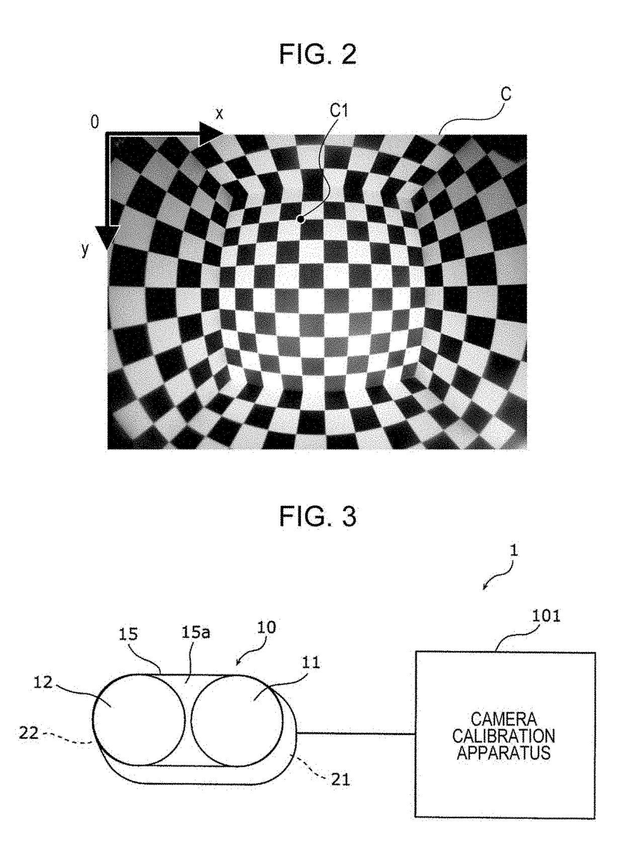
[0068]Reference to FIG. 3 shows a configuration of a camera system 1 including a camera calibration apparatus 101 according to Embodiment 1. The camera system 1 includes a multiple-lens camera 10 which has two or more lenses and a camera calibration apparatus 101 which calibrates camera parameters of the multiple-lens camera 10. The multiple-lens camera 10 includes multiple lenses 11 and 12 in one housing 15. Note that the multiple-lens camera 10 may include separate multiple cameras each of which includes a lens. Note that although no limitation is intended, the multiple-lens camera 10 in the embodiment is a stereo camera and is capable of stereo distance measurement of the position of a subject. Such a camera system 1 may be mounted on a moving object, for example, a vehicle, a marine vessel, and flying body. The vehicle may be, for example, an automobile, a truck, a bus, a two-wheeler, a transportation vehicle, a railed vehicle, a constructi...

embodiment 2

[0123]A description is provided for a camera calibration apparatus according to Embodiment 2. The configuration of the camera calibration apparatus according to Embodiment 2 is the same as that of Embodiment 1. Some of the operations of the camera calibration apparatus according to Embodiment 2 are different from those of Embodiment 1. To be more specific, while Embodiment 1 uses the weights wk as the view angle-corresponding lengths as indicated in Equation 4 described above when calculating the evaluation value J at step S305 of the camera parameter calculation process S300 illustrated in FIG. 8, Embodiment 2 uses the weights wk as normalized view angle-corresponding lengths. Hereinafter, Embodiment 2 is described mainly on the points different from Embodiment 1.

[0124]Reference to FIG. 11 shows a flowchart illustrating an example of the operation flow of the camera calibration apparatus according to Embodiment 2. The camera calibration apparatus according to Embodiment 2 performs ...

embodiment 3

[0128]A description is provided for a camera calibration apparatus according to Embodiment 3. The configuration of the camera calibration apparatus according to Embodiment 3 is the same as that of Embodiment 1. Some of the operations of the camera calibration apparatus according to Embodiment 3 are different from those of Embodiment 1. To be more specific, while Embodiment 1 uses the weights wk as the view angle-corresponding lengths as indicated in Equation 4 described above when unifying the evaluation value J at step S305 of the camera parameter calculation process S300 illustrated in FIG. 8, the weight wk in Embodiment 3 is the corresponding view angle-corresponding length if the view angle-corresponding length is larger than a threshold and the weight wk is 0 if the corresponding view angle-corresponding length is equal to or less than the threshold. Hereinafter, Embodiment 3 is described mainly on the points different from Embodiment 1.

[0129]Reference to FIG. 12 shows a flowch...


PUM


Abstract

A camera calibration method, which calculates camera parameters of two cameras using calibration points, includes: (a1) acquiring three-dimensional coordinate sets of the calibration points and image coordinate pairs of the calibration points in a camera image of each camera; (a2) acquiring multiple camera parameters of each camera; (a3) for each calibration point, calculating a view angle-corresponding length corresponding to a view angle of the two cameras viewing the calibration point; (a4) for each calibration point, calculating a three-dimensional position of a measurement point corresponding to a three-dimensional position of the calibration point using parallax of the calibration point between the two cameras; (a5) for each calibration point, weighting a difference between the three-dimensional coordinate set of the calibration point and the three-dimensional position of the measurement point corresponding to the calibration point using the view angle-corresponding length corresponding to the calibration point; and (a6) updating the camera parameters based on the weighted difference.

Description

BACKGROUND1. Technical Field[0001]The present disclosure relates to a camera calibration method, a recording medium, and a camera calibration apparatus.2. Description of the Related Art[0002]Calculation of camera parameters, in other words calibration of a camera requires a function which evaluates the camera parameters based on a two-dimensional coordinate pair on a two-dimensional image or a three-dimensional coordinate set in a three-dimensional space. The two-dimensional coordinate pair on the two-dimensional image is also referred to as an image coordinate pair, and the three-dimensional coordinate set in the three-dimensional space is also referred to as a world coordinate set. The evaluation function described above expresses the difference between the calculated camera parameters and the correct camera parameters, and if the calculated camera parameters coincide with the correct camera parameters, the evaluation function is 0. Camera calibration employing a conventional eval...

Claims


Application Information

Patent Timeline
IPC IPC(8): G06T7/80G06T7/73
CPCG06T7/85G06T7/73G06T2207/30208G06T2207/10012G06T2207/30204
Inventor WAKAI, NOBUHIKOAZUMA, TAKEONOBORI, KUNIOSATO, SATOSHI
Owner PANASONIC INTELLECTUAL PROPERTY MANAGEMENT CO LTD
Why Eureka
Try Eureka