This helps you quickly interpret patents by identifying the three key elements:
Problems solved by technology
Method used
Benefits of technology
Benefits of technology
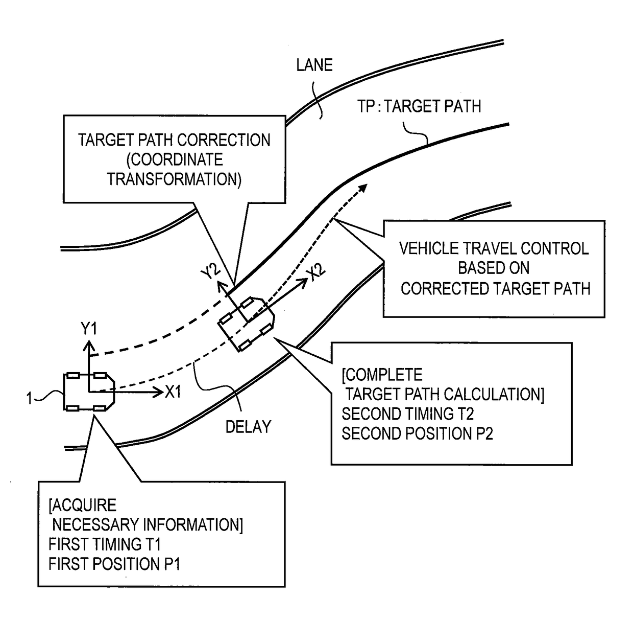
This patent describes a technique to improve the performance of an autonomous driving system by reducing delays in controlling the vehicle to follow a target path. The technique uses a method called target path correction to reduce the impact of control delay, which can make the vehicle uncomfortable and cause anxiety for the occupants. By correcting the target path, the system can achieve higher control accuracy and reduce sensory input from the occupants. This improvement in performance increases the confidence of the autonomous driving system. Additionally, the technique avoids complicated prediction processing and reduces the computational load by performing simple coordinate transformation. Overall, the patent provides a technique to increase path-following performance with suppressing computation load and reducing delays in controlling the vehicle's path.
Problems solved by technology
In the path-following control, control delay may occur due to various factors.
Such the calculation time required for calculating the target path causes the control delay.
The control delay of the path-following control causes decrease in performance of following the target path.
When the path-following performance of the autonomous driving system is decreased, an occupant of the vehicle feels senses of anxiety and strangeness, which leads to decrease in confidence in the autonomous driving system.
However, predicting the vehicle motion state and the obstacle state requires complicated computation processing, which causes increase in computation load, computation time, and computational resource.
Moreover, complicated computation processing is unnecessary for the target path correction processing.
Method used
Image
Click on the blue label to locate the original text in one second.
Reading with bidirectional positioning of images and text.
Examples
first embodiment
1. First Embodiment
1-1. Outline of Path-Following Control by Autonomous Driving System
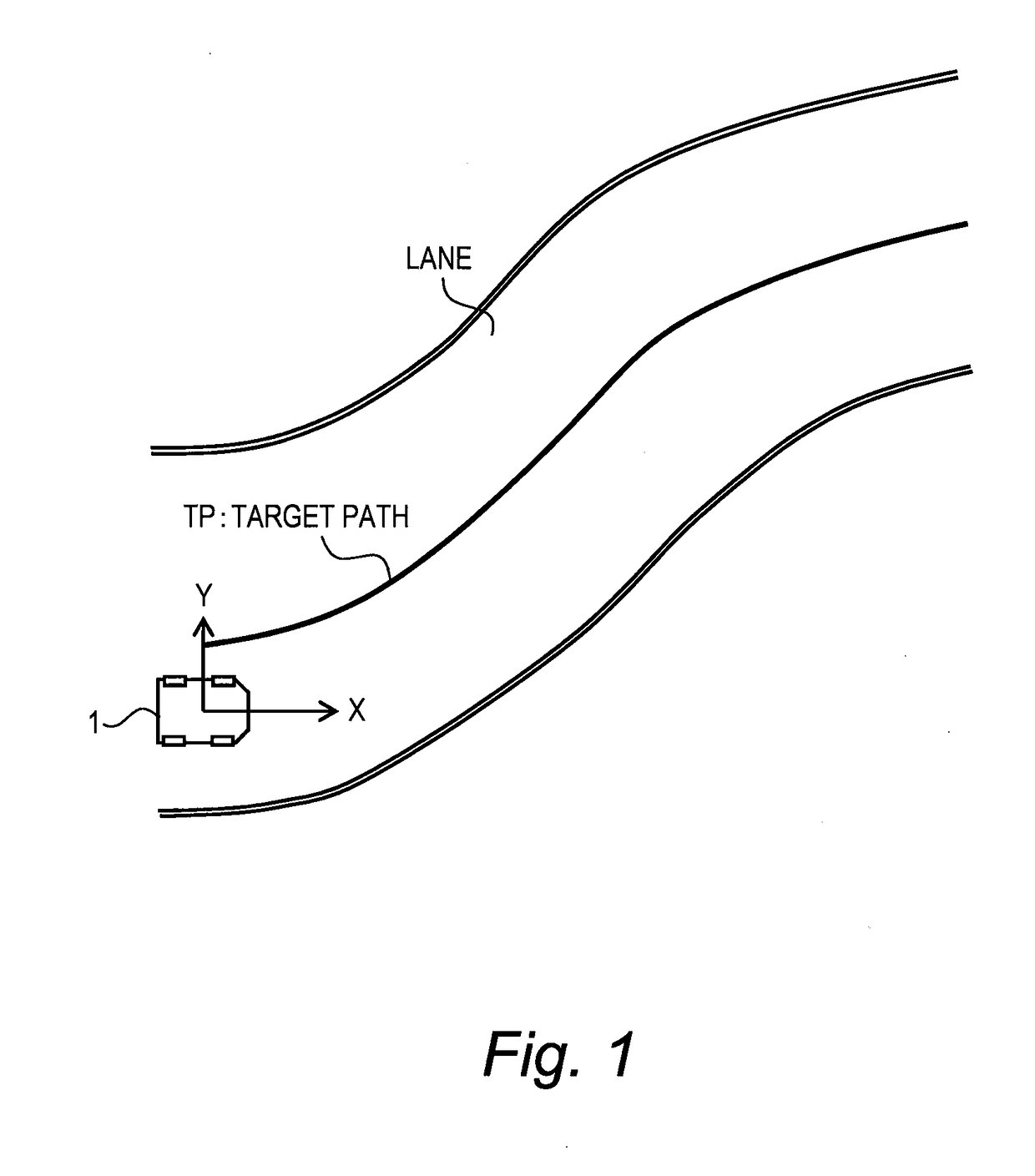
[0056]FIG. 1 is a conceptual diagram for explaining path-following control by an autonomous driving system according to the present embodiment. The autonomous driving system is mounted on a vehicle 1 and controls autonomous driving of the vehicle 1. The path-following control is a kind of the autonomous driving control. More specifically, in the path-following control, the autonomous driving system periodically calculates a target path TP for the vehicle 1, and controls travel of the vehicle 1 so as to follow the latest target path TP.
[0057]Here, let us define a vehicle coordinate system (X, Y). The vehicle coordinate system is a relative coordinate system fixed to the vehicle 1 and varies with motion of the vehicle 1. That is, the vehicle coordinate system is defined by a position and an orientation of the vehicle 1. In the example shown in FIG. 1, the X-direction is a front direction of the vehic...
modification example
1-5. Modification Example
[0105]The delay time from the first timing T1 to the second timing T2 is not necessarily limited to the target path calculation time. For example, the delay time from the first timing T1 to the second timing T2 may be set in consideration of the information communication time, the actuatorresponse time, and the like.
[0106]When the delay time from the first timing T1 to the second timing T2 is the target path calculation time, the delay time may be actually measured, instead of giving a predetermined value as the delay time. More specifically, at the above-described Step S30, the target path calculation unit 123 measures a processing time of the target path calculation processing and outputs the measurement result to the target path correction unit 124. The target path correction unit 124 can recognize the second timing T2 and the second coordinate system based on the measurement result.
second embodiment
2. Second Embodiment
2-1. Outline
[0107]The necessary information 90 necessary for calculating the target path TP is periodically acquired and updated. Every time the necessary information 90 is updated, the target path TP is determined and updated as well. In the following description, a suffix “k−1” represents the previous and a suffix “k” represent the latest.
[0108]FIGS. 12 and 13 show an example of updating of the necessary information 90 and the target path TP. At the previous first timing T1(k−1), the previous necessary information 90 is acquired. At the previous second timing T2(k−1), the previous target path TP(k−1) is obtained. At the first timing T1(k), the new necessary information 90 is acquired. At the second timing T2(k), the new target path TP(k) is obtained. That is, the target path TP is updated.
[0109]During a period from the first timing T1(k) to the second timing T2(k), the new target path TP(k) is under calculation and not yet determined. Therefore, during the peri...
PUM
Abstract
An autonomous driving system mounted on a vehicle determines a target path based on necessary information and performs vehicle travel control such that the vehicle follows the target path. A first coordinate system is a vehicle coordinate system at a first timing when the necessary information is acquired. A second coordinate system is a vehicle coordinate system at a second timing later than the first timing. The autonomous driving system calculates, based on the necessary information acquired at the first timing, a first target path defined in the first coordinate system. Then, the autonomous driving system corrects the first target path to a second target path defined in the second coordinate system by performing coordinate transformation from the first coordinate system to the second coordinate system. The autonomous driving system uses the second target path as the target path to perform the vehicle travel control.
Description
BACKGROUNDTechnical Field[0001]The present disclosure relates to an autonomous driving system. In particular, the present disclosure relates to an autonomous driving system that controls travel of a vehicle to follow a target path.Background Art[0002]Patent Literature 1 discloses a vehicle travel support device that supports travel of a vehicle. The vehicle travel support device calculates a control command value for avoiding an obstacle, based on vehicle motion state and obstacle state detected by sensors. More specifically, the vehicle travel support device calculates both a low-precision first control command value and a high-precision second control command value. A time required for calculating the high-precision second control command value is longer than a time required for calculating the low-precision first control command value. That is, calculation delay occurs when calculating the second control command value. In order to compensate for such the calculation delay, the ve...
Claims
Application Information
Patent Timeline
Application Date:The date an application was filed.
Publication Date:The date a patent or application was officially published.
First Publication Date:The earliest publication date of a patent with the same application number.
Issue Date:Publication date of the patent grant document.
PCT Entry Date:The Entry date of PCT National Phase.
Estimated Expiry Date:The statutory expiry date of a patent right according to the Patent Law, and it is the longest term of protection that the patent right can achieve without the termination of the patent right due to other reasons(Term extension factor has been taken into account ).
Invalid Date:Actual expiry date is based on effective date or publication date of legal transaction data of invalid patent.

