Resolver

a technology of a solution and a ring, which is applied in the field of resolution, can solve problems such as external noise and errors in detecting rotation angles, and achieve the effects of reducing interference between magnetic fluxes, improving product performance, and improving accuracy

Active Publication Date: 2018-10-25
LS AUTOMOTIVE TECH CO LTD
View PDF6 Cites 0 Cited by
  • Summary
  • Abstract
  • Description
  • Claims
  • Application Information

AI Technical Summary

Benefits of technology

[0038]The resolver of the present disclosure may precisely measures a rotation angle of a rotating device such as a motor since the resolver is robust against external noise and has an output waveform of enhanced accuracy.
[0039]The resolver of the present disclosure may have improved product performance by reducing interference between magnetic fluxes generated at adjacent teeth.

Problems solved by technology

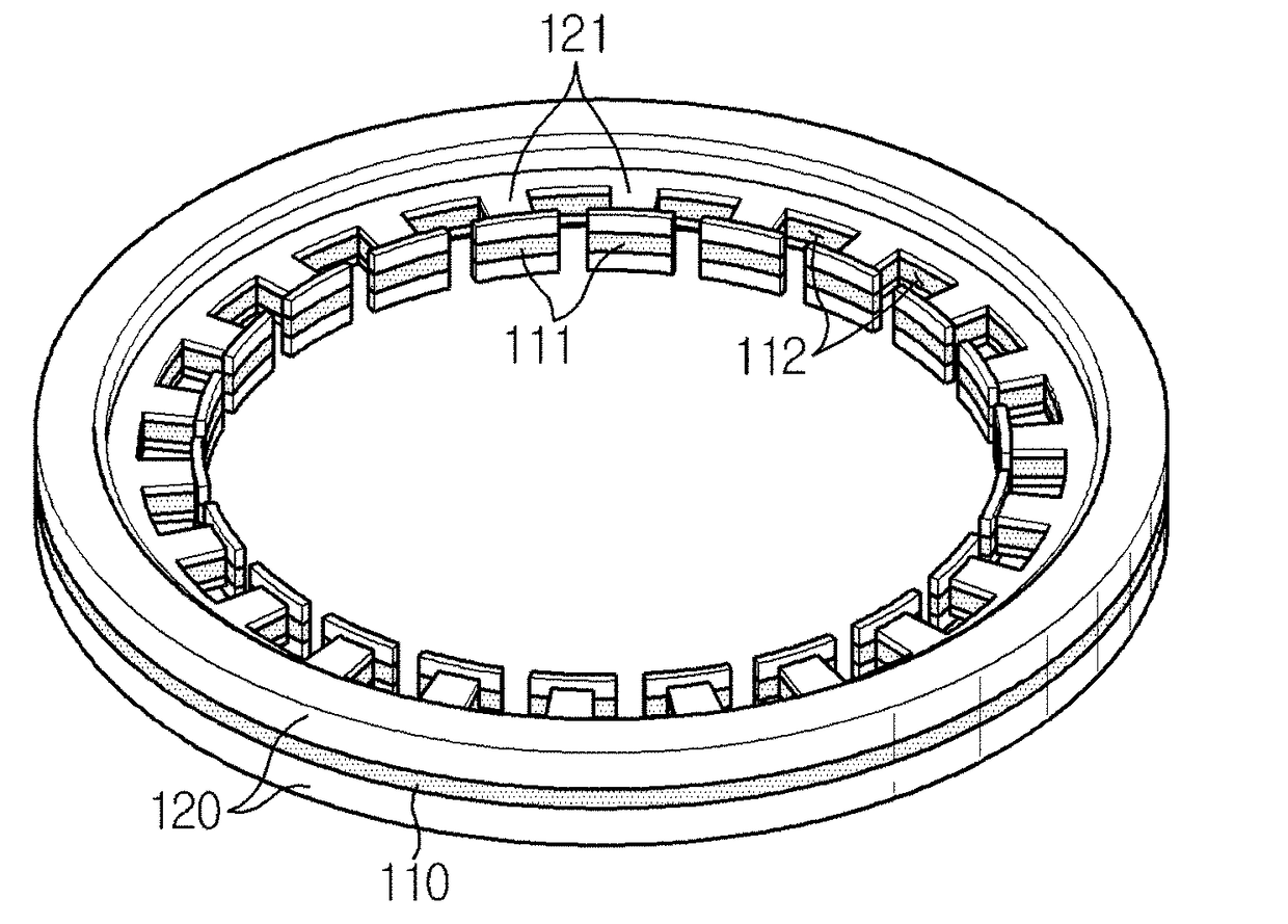
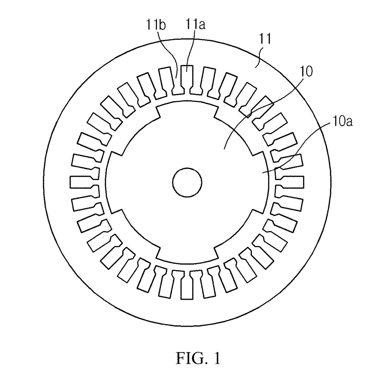
For example, when the coil is wound, if the coil is would irregularly, a high-frequency wave may be generated at an outer waveform, or electric interference may be caused between coils wound on two adjacent teeth 11b, thereby generating an error in detecting a rotation angle.
In addition, if a coil is wound more on the teeth 11b, an area occupied by the coil at the slot 11a between the teeth 11b increases, which causes electric interference between coils wound on two adjacent teeth 11b and results in an error.
If a coil is wound less on the teeth 11b, a transformation ratio of an induced voltage of the output coil is lowered, which becomes vulnerable to external noise.

Method used


Image

  • Resolver
  • Resolver
  • Resolver

Examples


Embodiment Construction

0.9931.0050.9820.258Example 20.9751.0230.9540.263Example 30.9521.0490.9160.265Example 40.9371.0610.8860.272Example 50.9291.070.8510.275Example 60.911.0890.8250.288Example 70.8921.0990.8030.298Example 80.8751.1090.7590.352Example 90.8581.1490.720.412Example 100.8411.1520.6980.475Comparative Example 10.8241.1780.6490.525Comparative Example 20.8021.1950.6120.567Comparative Example 30.7951.2070.5880.602Comparative Example 40.7731.2290.5430.627

[0071]FIG. 8 is a graph showing a maximum error rate of each sample resolver according to lmin / lmax ratio, FIG. 9 is a graph showing a maximum error rate of each sample resolver according to lmean / lmax ratio, and FIG. 10 is a graph showing a maximum error rate of each sample resolver according to lmean / lmin ratio. In other words, FIGS. 8, 9 and 10 express Table 1 with graphs.

[0072]Referring to Examples 1 to 10 of Table 1 and FIG. 8, when the lmin / lmax ratio is used as a basis, if the lmin / lmax ratio is 0.69 or above and 1 or below, the maximum erro...


PUM


Abstract

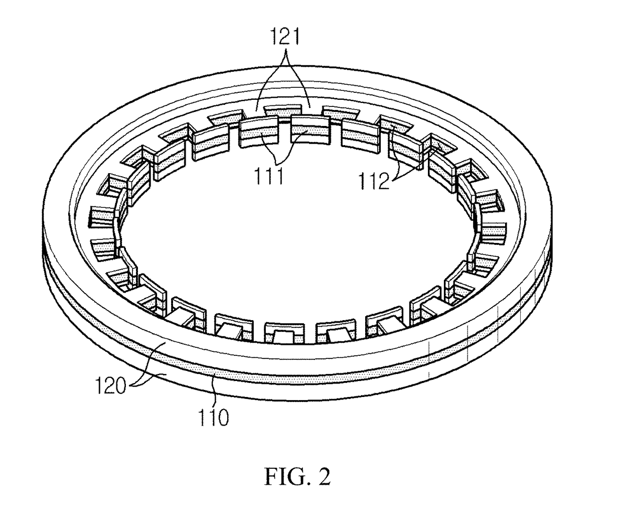
Disclosed is a resolver robust against external noise and having a reduced error in the detection of a rotation angle, which includes a stator made of a magnetic material and having a plurality of teeth and a plurality of slots alternately formed at an inner side thereof, insulation covers respectively having a tooth insulating unit formed at an inner side thereof corresponding to the teeth and mounted to the stator at both upper and lower surfaces of the stator, and coils wound on the teeth with the tooth insulating unit being interposed therebetween, wherein regarding winding widths of coils located at an outermost circumference among the wound coils, a ratio of a shortest winding width to a longest winding width is 0.69 or above and 1 or below.

Description

TECHNICAL FIELD[0001]The present application claims priority to Korean Patent Application No. 10-2015-0159831 filed on Nov. 13, 2015 in the Republic of Korea, the disclosures of which are incorporated herein by reference.[0002]The present disclosure relates to a device for detecting a rotation angle of a rotating device, and more particularly, to a resolver.BACKGROUND[0003]When controlling a rotating device, for example a motor, rotation information should be detected precisely and rapidly. When controlling a rotating device, a movement or rotating location of a rotating body should be measured accurately by means of a rotation angle detecting device installed at a rotary shaft. A resolver and an encoder have been adopted and used for such measurement, and these detecting devices have advantages and disadvantages. The resolver directly detects an absolute location of a rotor and calculates a rotating direction and a rotating speed by means of the change of location of the rotor.[000...

Claims


Application Information

Patent Timeline
Patent Type & Authority Applications(United States)
IPC IPC(8): G01D5/244G01D5/245H02K24/00
CPCG01D5/24433G01D5/245H02K24/00G01D5/20G01B7/30G01D5/2046
Inventor LEE, WON-YONGNA, BYUNG-CHEOLSIM, DA-HEELEE, SEONG-WOOKCHOI, YEON-MUK
Owner LS AUTOMOTIVE TECH CO LTD
Why Eureka
Try Eureka