Eureka AIR delivers breakthrough ideas for toughest innovation challenges, trusted by R&D personnel around the world.

Universal control module for electrical lock, retrofit and method for operating

Active Publication Date: 2018-11-01
DANALOCK IVS
View PDF0 Cites 4 Cited by
  • Summary
  • Abstract
  • Description
  • Claims
  • Application Information

AI Technical Summary

Benefits of technology

The patent describes a system that allows people to lock and unlock their doors using their smartphone. This is done through a computer application that controls the lock on the smartphone. Additionally, the system can be used with existing electromechanical or magnetic door locks, or even new locks that have simple mechanisms. Overall, the system adds more convenience and functionality to existing door locks without requiring any additional components.

Problems solved by technology

However, the change from an older, simpler lock type to the modem advanced lock system is an expensive and mechanically not always easy task.
Especially, the fitting of the door lock inside door panels may require that the door itself is modified or changed, which is often not desired.
Also, the existing remote operation of door locks typically has to be changed, which is not always wanted, especially when a certain system is well established.
If the encryption key is not valid, the decryption may not be carried out, and the external control unit does not perform any locking or unlocking action.
Thus, in the case where the unlocking or locking action is performed prior to the predetermined time limit, this action overrules the predetermined time limit and the encryptions key loses its validity as soon as the locking or unlocking is performed, even in the event that the predetermined time limit is later than the decryption and execution of the operation command.
For example, in the event of locking by an authorized person, unauthorized third parties cannot use the same encryption key for a subsequent unlocking action, even if the time span between the locking and unlocking is short.

Method used


Image

  • Universal control module for electrical lock, retrofit and method for operating
  • Universal control module for electrical lock, retrofit and method for operating
  • Universal control module for electrical lock, retrofit and method for operating

Examples


Embodiment Construction

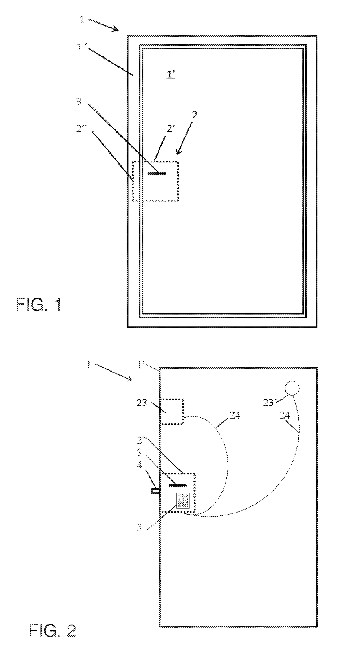
[0058]FIG. 1 illustrates a door 1 with a door panel 1′ that is swinging in and out of a frame 1″. The door 1 comprises a door lock 2 with a first lock part 2′ in the door panel 1′ and a second lock part 2″ in the frame 1″. The first lock part 2′ and the second lock part 2″ are interacting for locking the door 1. For example, the first lock part 2′ is a lock module with a movable lock bolt and the second lock part 2″ is a recess in which the lock bolt engages for locking. Alternatively, the second lock part 2″ is a movable strike faceplate that releases a lock bolt from the locked position by moving away from the lock bolt. A further alternative is a magnetic lock, where a magnetic field is electrically created to hold an electromagnet against an opposite magnetically interacting pole.

[0059]In the following, the device is explained in relation to a movable lock bolt, however, the principles are universal and also apply for all three types of locks as mentioned above as well as furthe...


PUM


Abstract

A control unit for retrofit to electromechanical or magnetic door locks is provided. The control unit includes a casing with an electrical exits port that is connected to the electrical connectors of a standard electromechanical door lock in order to provide an additional way of controlling the lock. Especially, the external control unit receives lock commands from a mobile device, such as a telephone, for locking or unlocking the door lock.

Description

CROSS-REFERENCE TO RELATED APPLICATIONS[0001]This application claims priority to PCT Application No. PCT / DK2016 / 050341 having a filing date of Oct. 27, 2016, which is based on DK Application No. PA 2015 70698, having a filing date of Oct. 29, 2015, the entire contents both of which are hereby incorporated by reference.FIELD OF TECHNOLOGY[0002]The following relates to wireless control modules for electromechanical locks. In particular, it relates to retrofit of a control unit to an already existing electrically operated door lock in order to provide a secondary tool for operating an existing lock.BACKGROUND[0003]Electromechanical door locks are operated by various methods, for example by a wired remote control, which in the simplest form is a push button provided remotely from the door, for example in an apartment remotely from the entrance door of the building. For accessing a building, it is also known to use keypads that are configured to open a lock when receiving an input of a p...

Claims


Application Information

Patent Timeline
IPC IPC(8): E05B47/02G07C9/00E05B47/00
CPCE05B47/026G07C9/00571E05B47/0002G07C2009/00634G07C2009/00769E05B2047/0058E05B2047/0091G07C9/00G07C9/00174E05B2047/0057E05B2047/0095
Inventor OVERGAARD, HENNING
Owner DANALOCK IVS
Why Eureka
Eureka Blog
Learn More