
Pipeline inspection robot

a technology for inspection robots and pipelines, applied in the field of mobile robots, can solve the problems of pipelines that are “unpiggable”, inspection and maintenance generate huge costs, and suffer from several diseases, so as to reduce costs, less customization, and shorten learning time

Inactive Publication Date: 2018-11-01
NATIONAL GRID GAS PLC
View PDF0 Cites 32 Cited by
  • Summary
  • Abstract
  • Description
  • Claims
  • Application Information

AI Technical Summary

Benefits of technology

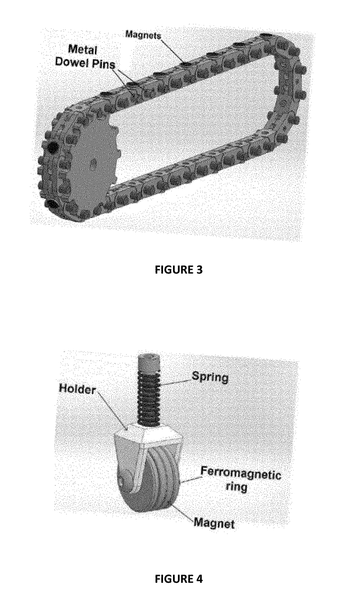
The present invention provides a robot that can travel through a pipeline. The robot has a streamlined aerofoil shape that promotes pressing of the robot to the internal wall of the pipeline. The robot can be a single robot or a group of robots that move generally parallel to the pipeline and can communicate with each other. The robot can be controlled by constant feedback between the robots or a system of constant feedback between all the robots. The robot can be designed with a modular design that allows for easy creation and use in different systems. The patent text also describes the use of magnetic roller means and magnetic tracked drive means for the robot.

Problems solved by technology

Typical pipe constructions such as sewers, gas / oil transmission pipelines, gas / oil distribution pipes are suffering from several diseases when getting old.
Aging, corrosion and mechanical stress generally lead to the loss of material thickness or generation of cracks that can cause leakages or sometimes the destruction of the pipeline construction
Since many of these constructions have not been designed to optimize automatic inspection and repair tasks, inspection and maintenance generate huge costs, especially if disassembling or even excavating is necessary.
However, some pipelines are “unpiggable”, for example because a free swimming tool can't be introduced or removed.
Other barriers to pigging are insufficient flow to overcome friction and drive a pig, multi-diameters pipes or internal obstacles.
However, none of these systems can deal with narrow pipe environments which integrate high abrupt diameter changes and bends and also require climbing ability.
These robots take advantage of the magnetic force in order to travel on surfaces with any inclination, however, their mobility is limited to smooth obstacle-free surfaces.
In addition, internal obstacles such as bends and pipeline fittings (T-branches, Y-branches), and any inclination can be encountered.

Method used


Image

  • Pipeline inspection robot
  • Pipeline inspection robot
  • Pipeline inspection robot

Examples


Embodiment Construction

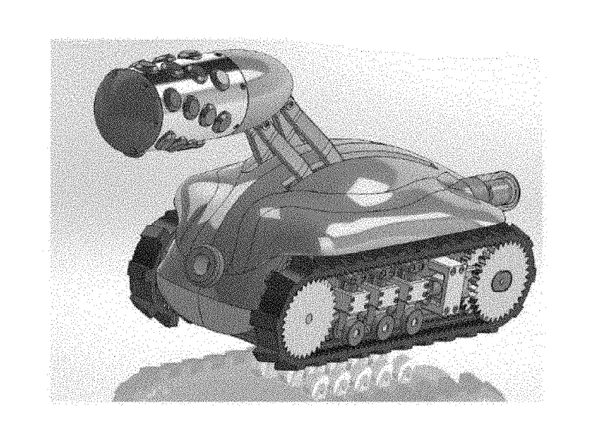
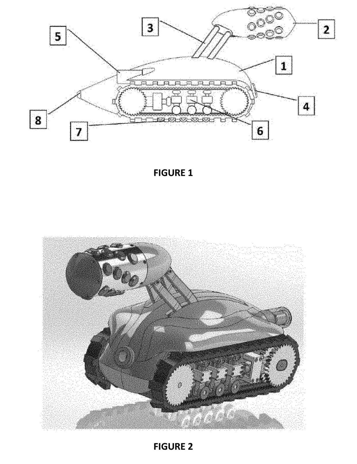
[0061]An inventive robot according to one embodiment of the invention is schematically illustrated in FIG. 1. It includes a streamlined aerofoil shaped (low profile) body 1 with NDT articulation arm 3 mounted on a top. By means of the articulation system 3 the modular NDT scanning module 2 can be risen to the centre of pipe (in range of DN600 to DN900). The device drive while monitoring the inside of the pipe by forward-looking field camera 4. During normal operation and reversing the umbilical cable used for data and control signal transmission is observed by rear facing camera 5. Further, the shape of the tracks is adapted to complex pipe geometry and to increase the contact surface area. The suspension system 6 allows the tracks to bend and keep constant traction and required tension. A series of magnetic free rolling wheels 7 increase traction and allows the robot to navigate vertical and incline segment of the pipe. The data and control signals are transmitted through an umbili...


PUM


Abstract

The present invention provides a robot which is suitable for travel through a pipeline. The inventive robot comprises at least one tracked drive means and at least one roller means that can swivel about an axis substantially normal to a rolling axis thereof, wherein said at least one tracked drive means and at least one roller means are provided with magnetic means for generating a magnetic adhesion force between the robot and an internal wall of the pipeline.

Description

TECHNICAL FIELD[0001]The present invention relates to a mobile robot for internally inspecting pipelines, a robotic system comprising two or more such robots and to a method for pipeline inspection as defined in the present independent claims.BACKGROUND OF THE INVENTION[0002]Typical pipe constructions such as sewers, gas / oil transmission pipelines, gas / oil distribution pipes are suffering from several diseases when getting old. (Note: A “pipeline” or “pipe” may alternatively be termed simply as “conduit”, and as used herein such terms may be used interchangeably). Aging, corrosion and mechanical stress generally lead to the loss of material thickness or generation of cracks that can cause leakages or sometimes the destruction of the pipeline construction[0003]Thus, periodic inspection of the pipe system is required in order to prevent such damages. Since many of these constructions have not been designed to optimize automatic inspection and repair tasks, inspection and maintenance g...

Claims


Application Information

Patent Timeline
IPC IPC(8): G01M3/00F16L55/32G01M3/40G01N33/00G01N21/3504G01N29/12B25J5/00B62D55/02B60B33/00B60B33/08B60B19/00G05D1/02H04N7/18G06K9/00
CPCG01M3/005F16L55/32G01M3/40G01N33/0047G01N21/3504G01N29/12B25J5/005B62D55/02B60B33/00B60B33/08B60B19/006G05D1/021H04N7/185G06K9/00664F16L2101/30G01N2021/3595G01N2291/0289G05D2201/0207B60B19/003B62D55/265B60B33/0028B60B33/0063B60Y2200/40B60Y2200/60F16L55/30F16L55/40G06V20/10
Inventor CICHOSZ, RAFALWHITE, JOHNPRICE, TOMBARKER, CHRIS
Owner NATIONAL GRID GAS PLC
Learn More