
Ultralight Photovoltaic Power Generation Tiles

a photovoltaic power generation and ultralight technology, applied in the field of space-based solar power stations, can solve the problems of reducing the economic viability of such sbsp systems, increasing the collection rate of solar energy, and reducing the size of sbsp systems to generate sufficient electrical power, etc., to achieve the effect of improving thermal emissivity

Pending Publication Date: 2018-11-01
CALIFORNIA INST OF TECH
View PDF3 Cites 18 Cited by
  • Summary
  • Abstract
  • Description
  • Claims
  • Application Information

AI Technical Summary

Benefits of technology

The invention provides a photovoltaic concentrator tile for a space-based solar power system, which includes a photovoltaic cell, a reflector, a power transmitter, and circuitry for controlling functions. The tile has a compactible structure, materials for improving thermal emissivity, and methods for manufacturing and using these components. The reflector has a reflective face that directs incoming light towards the photovoltaic cell. The power transmitter is connected to the ground layer using a strut, and the power transmission layer is attached to the ground layer using a polyimide layer. The reflector may have a thermally emissive surface, which may be made of polyimide or a metallic layer. The power generation tile may have multiple reflectors and photovoltaic cells, where each reflector directs light onto an individual photovoltaic cell. The reflector is a parabolic concentrator or a plurality of S-springs. The power generation tile may also include a radiator for dissipating heat accumulated by the photovoltaic cell. The reflector body may be made of carbon fiber, which may be a 3-ply, 4-ply, or 8-ply layup. The invention provides a compactible and efficient photovoltaic concentrator tile for space-based solar power systems.

Problems solved by technology

Basing such a system in space results in a higher collection rate for the solar energy due to the lack of a diffusing atmosphere.
A general limitation for conventional SBSP systems is the size of SPS required to generate sufficient electrical power from solar energy.
The launch costs associated with placing such large structures into orbit reduces the economic viability of such SBSP systems.

Method used


Image

  • Ultralight Photovoltaic Power Generation Tiles
  • Ultralight Photovoltaic Power Generation Tiles
  • Ultralight Photovoltaic Power Generation Tiles

Examples


Embodiment Construction

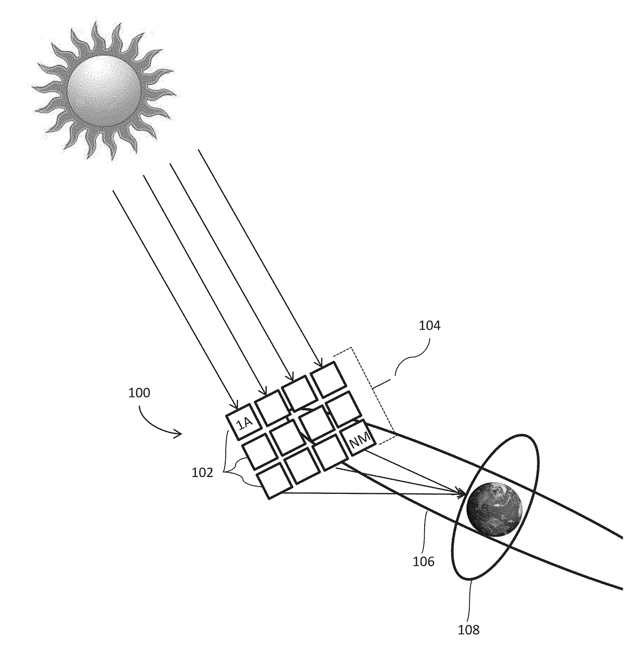
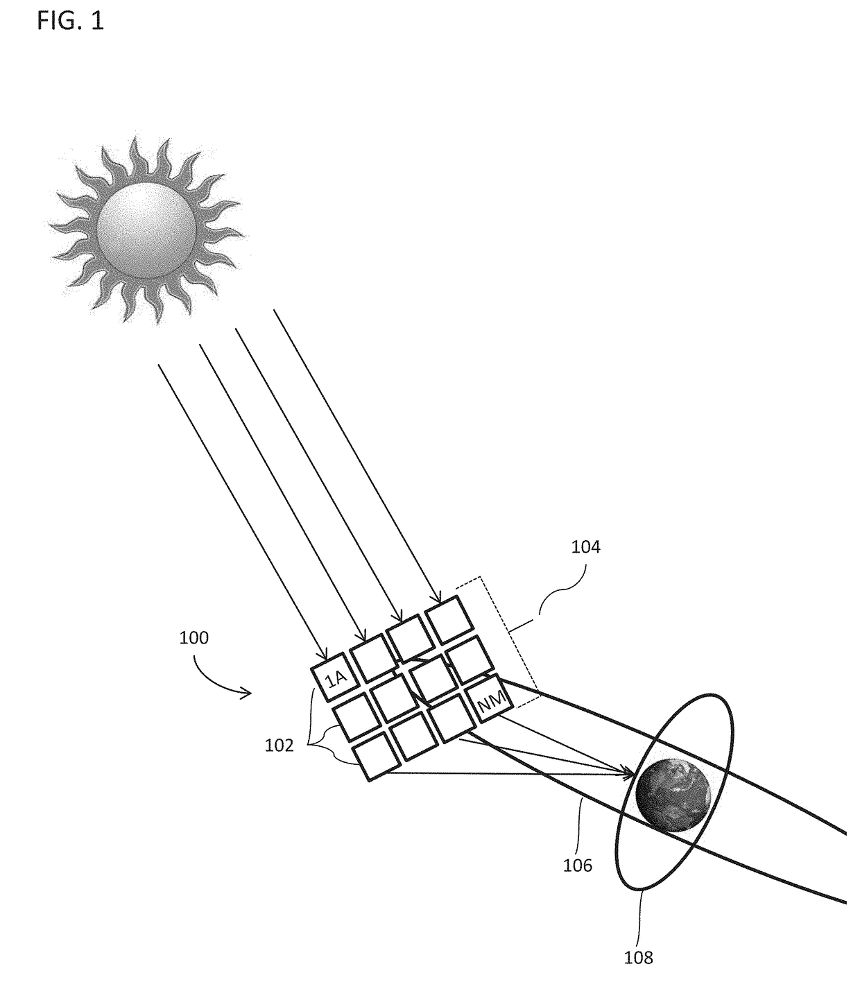
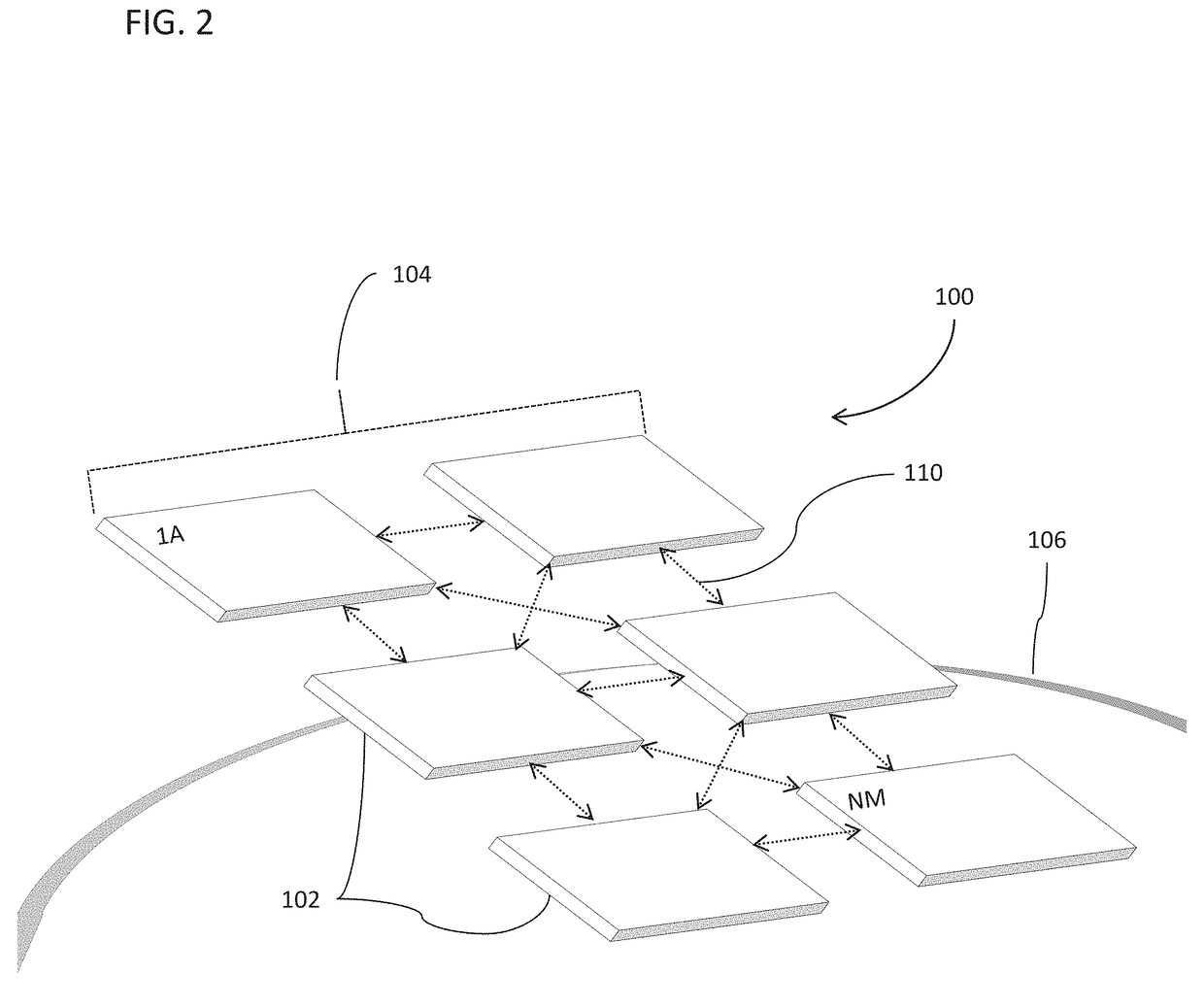
[0085]Turning now to the drawings, large-scale space-based solar power (SBSP) stations and efficient power generation tiles in accordance with various embodiments of the invention are illustrated. In many embodiments, the SBSP systems include arrays of independent satellite modules each incorporating arrays of independent solar electric power generation tiles. In several embodiments, the power generation tiles are each formed incorporating independent photovoltaic cells, power transmitters, and control circuits. The satellite modules and power generation tiles may be formed from compactible structures according to some embodiments. Methods for deploying, stabilizing, operating and constructing such large-scale space-based solar power systems in accordance with a number of embodiments of the invention are also described. Similar systems and methods are described in: U.S. provisional patent application Ser. No. 61 / 993,016 entitled “Large-Scale Space-Based Array: Packaging, Deployment ...


PUM


Abstract

Systems and methods in accordance with various embodiments of the invention provide a photovoltaic concentrator tile for a space-based solar power (SBSP) system including constituent components thereof. In a number of embodiments, the photovoltaic concentrator tile include a one photovoltaic cell, a reflector, a power transmitter and circuitry configured to perform a variety of control functions. Embodiments also provide compactible structures, materials for improving thermal emissivity, and methods and mechanisms for manufacturing and using these components.

Description

CROSS-REFERENCE TO RELATED APPLICATIONS[0001]This application is a continuation of U.S. patent application Ser. No. 14 / 728,985 entitled “Large-Scale Space-Based Solar Power Station: Efficient Power Generation Tiles,” filed Jun. 2, 2015, which claims priority to U.S. Provisional Patent Application Ser. No. 62 / 120,650 entitled “Large-Scale Space-Based Array: Packaging, Deployment and Stabilization of Lightweight Structures,” filed Feb. 25, 2015 and U.S. Provisional Patent Application Ser. No. 62 / 006,604 entitled “Large-Scale Space-Based Array: Efficient Photovoltaic Structures for Space,” filed Jun. 2, 2014; the disclosures of which is incorporated by reference herein in its entirety.[0002]This application is a continuation of U.S. patent application Ser. No. 15 / 233,828 entitled “Lightweight Structures for Enhancing the Thermal Emissivity of Surfaces,” filed Aug. 10, 2016, which claims priority to U.S. Provisional Patent Application Ser. No. 62 / 366,720 entitled “Space-based Solar Powe...

Claims


Application Information

Patent Timeline
Patent Type & Authority Applications(United States)
IPC IPC(8): H01L31/054B64G1/42H01L31/052H02S20/30H02S40/22B64G1/44H01L31/042H02J50/80
CPCH01L31/0547B64G1/428H01L31/052H02S20/30H02S40/22B64G1/443H01L31/042H02J50/80H02J50/30Y02E10/52B64G1/4282Y02E10/50
Inventor KELZENBERG, MICHAEL D.ATWATER, HARRY A.PELLEGRINO, SERGIOHAJIMIRI, SEYED ALIWARMANN, EMILY C.NAQAVI, ALILOKE, SAMUELROY, TATIANAVINOGRADOVA, TATIANAMESSER, ALEXANDERLECLERC, CHRISTOPHEGDOUTOS, ELEFTHERIOSHUANG, JING SHUN
Owner CALIFORNIA INST OF TECH
Learn More