Methods and systems for redox flow battery electrolyte hydration

a technology of electrolyte hydration and redox flow battery, which is applied in the direction of electrochemical generators, cell components, electrochemical stream management, etc., can solve the problems of heavy and cumbersome difficult transport of filling and hydration redox flow battery systems, and achieve the effect of minimal performance loss

Active Publication Date: 2018-11-01
ESS TECHNOLOGY
View PDF0 Cites 5 Cited by
  • Summary
  • Abstract
  • Description
  • Claims
  • Application Information

AI Technical Summary

Benefits of technology

[0004]Redox flow batteries are suitable for grid scale storage applications due to their capabilities of scaling power and capacity independently, and charging and discharging for thousands of cycles with minimal performance losses. Electrolyte, including aqueous solutions comprising water and salts and / or acids, are recirculated between electrolyte tanks and the redox flow battery cells in order to supply sufficient electrolyte to carry of the redox reactions for battery charging and discharging. Commissioning a new redox flow battery system traditionally involves hydrating and filling a redox flow battery system, including the electrolyte tanks, at a battery vendor's manufacturing facility, prior to transporting the redox flow battery system to and installing the redox flow battery system at the end-use location.

Problems solved by technology

Namely, a filled and hydrated redox flow battery system is heavy and cumbersome, and transport of filled and hydrated redox flow battery systems can be difficult and expensive.
Furthermore, transporting of redox flow battery systems between a battery vendor / manufacturing facility and an end-use site may involve various modes of transportation such as by truck, by rail, and by ship over large distances, which may be slower when the redox flow battery system is filled and hydrated.

Method used


Image

  • Methods and systems for redox flow battery electrolyte hydration
  • Methods and systems for redox flow battery electrolyte hydration
  • Methods and systems for redox flow battery electrolyte hydration

Examples


Embodiment Construction

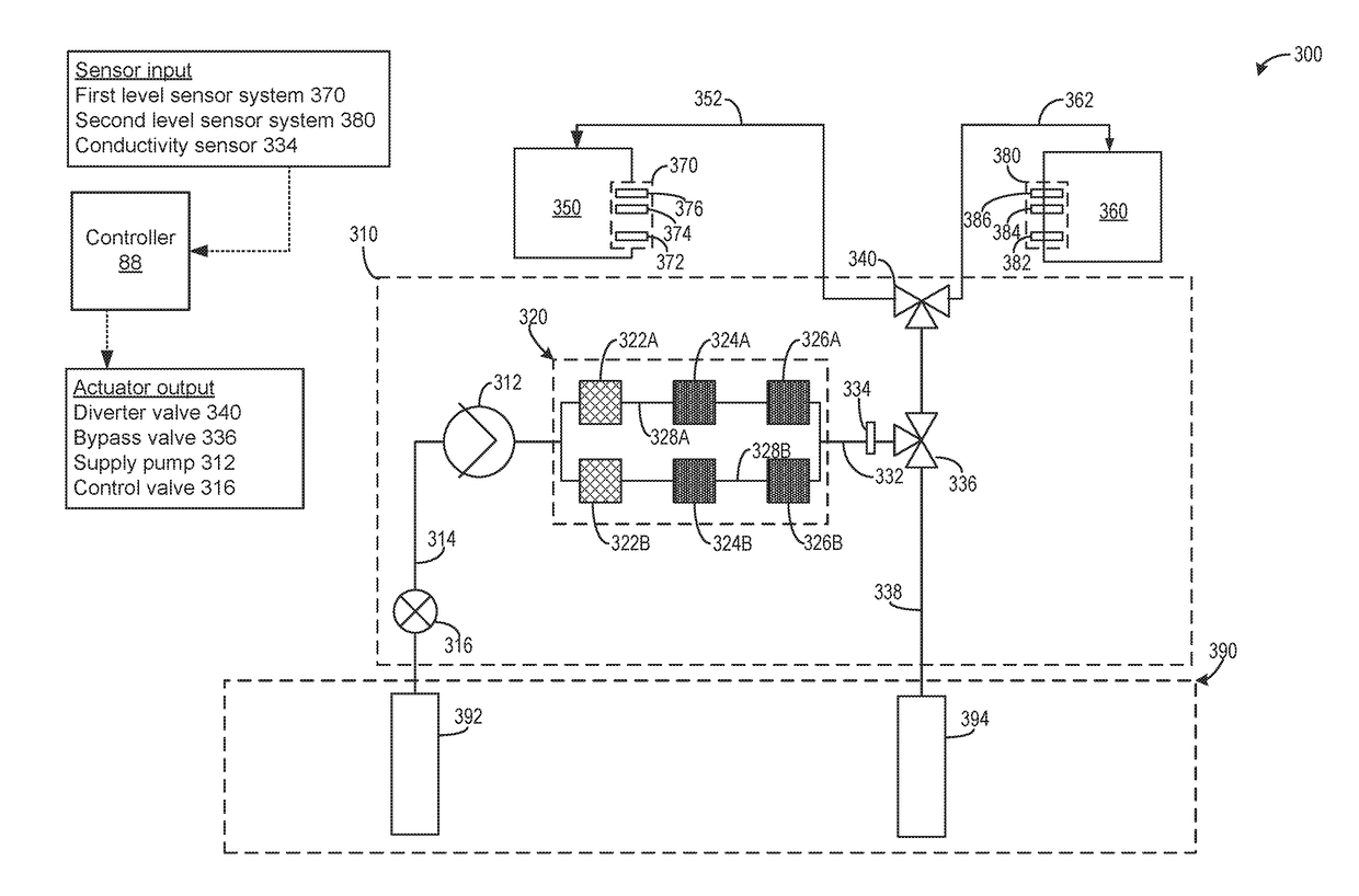
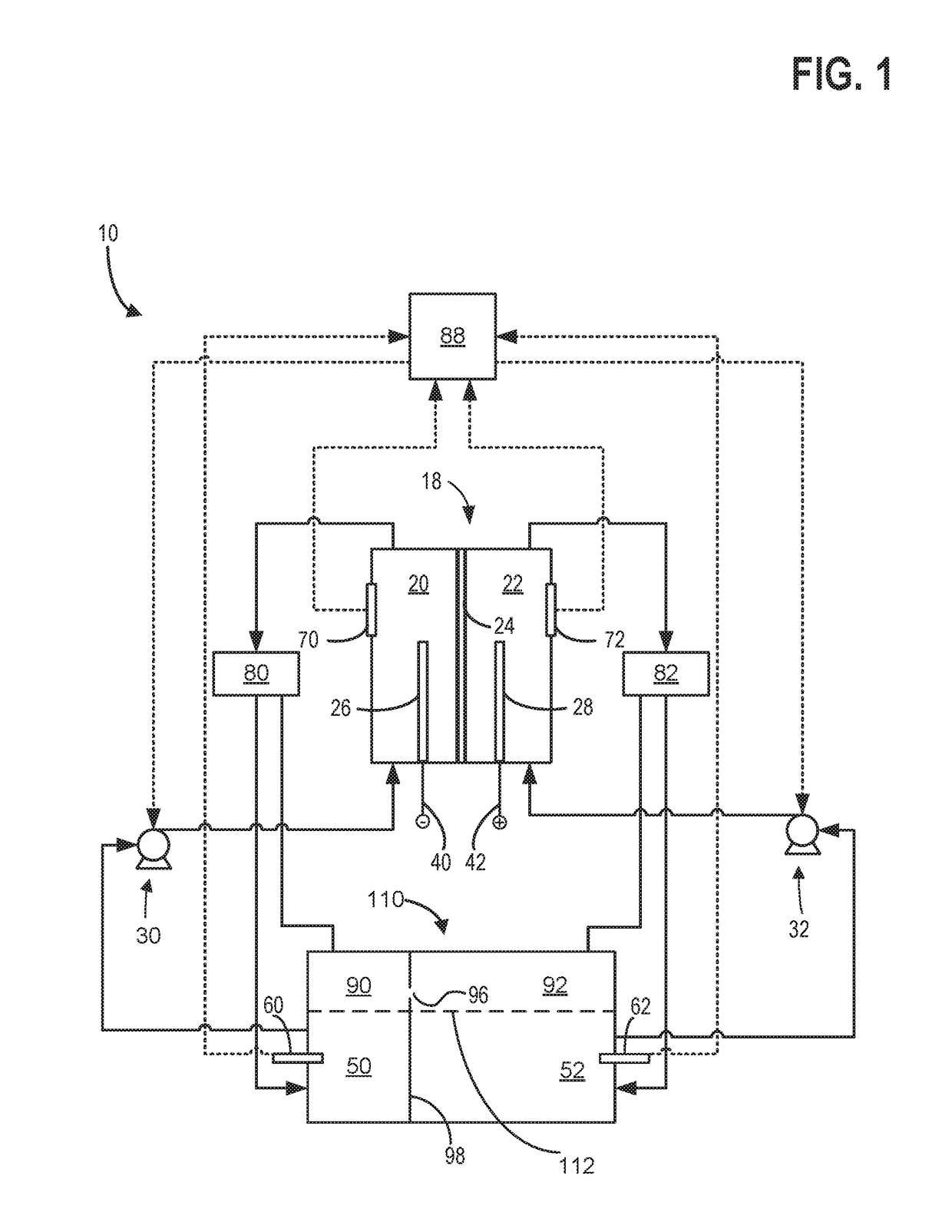
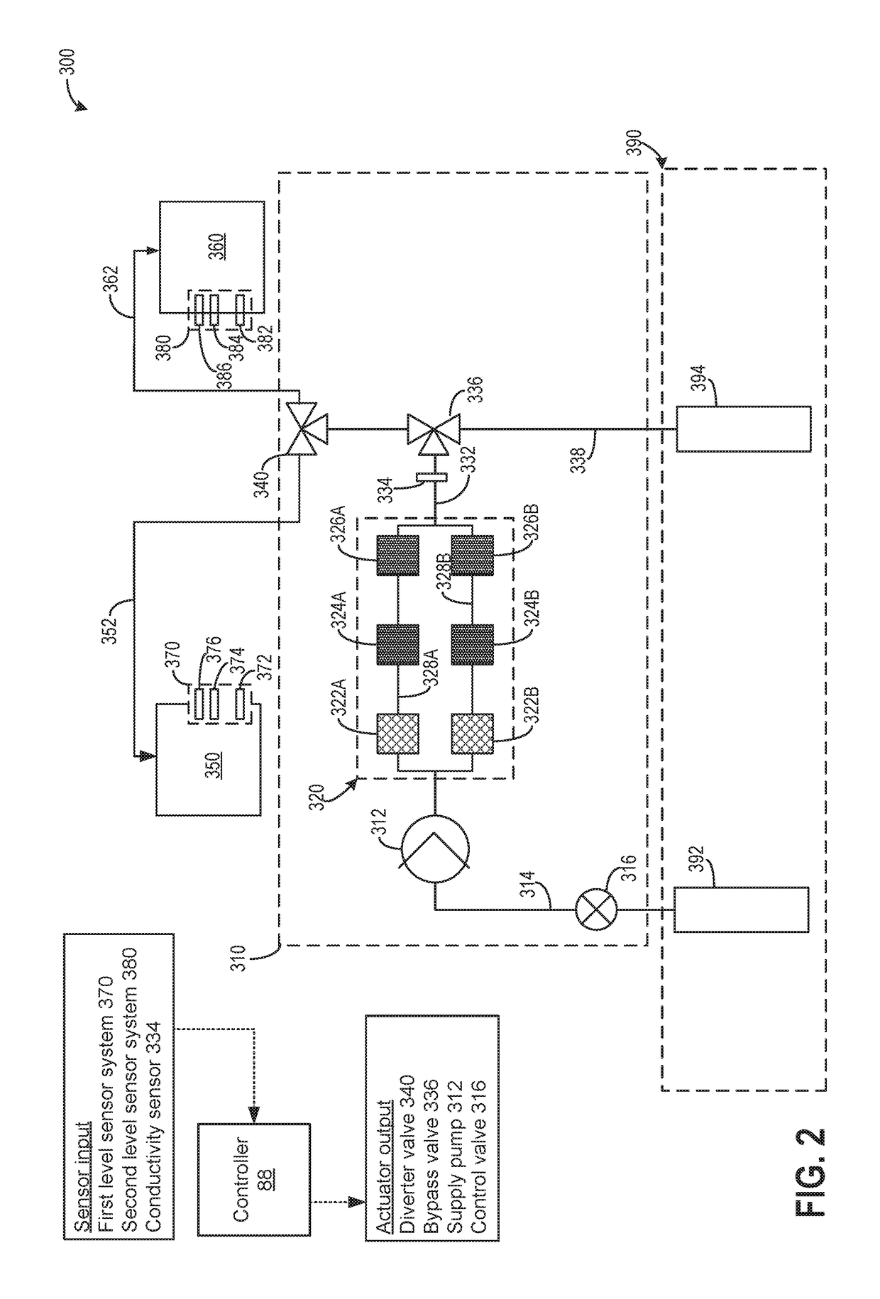
[0013]The following description relates to systems and methods for flowing water to electrolytes configured to store electrical energy for a redox flow battery. The redox flow battery is shown in FIG. 1 includes an integrated multi-chamber storage tank having separate positive and negative electrolyte chambers. Prior to installation and commissioning of the redox flow battery system, the redox flow battery system may be assembled and delivered to a desired end-use location, different from a location where the battery was assembled, with dry electrolyte stored in the positive and negative electrolyte chambers. The dry electrolyte includes electrolyte granules or precursors free of liquid water and / or other liquid solvents in a moisture free state. Once delivered to the end-use location, the assembled redox flow battery system may be installed thereat, thereby fixing a position of the redox flow battery system. A field hydration system, shown in FIG. 2, may be delivered to the end-use...


PUM

PropertyMeasurementUnit
concentrationaaaaaaaaaa
temperatureaaaaaaaaaa
threshold temperatureaaaaaaaaaa

Abstract

Methods and systems are provided for transporting and hydrating a redox flow battery system with a portable field hydration system. In one example, the redox flow battery system may be hydrated with the portable field hydration system in a dry state, in the absence of liquids. In this way, a redox flow battery system may be assembled and transported from a battery manufacturing facility to an end-use location off-site while the redox flow battery system is in the dry state, thereby reducing shipping costs, design complexities, as well as logistical and environmental concerns.

Description

CROSS REFERENCE TO RELATED APPLICATIONS[0001]The present application claims priority to U.S. Provisional Application No. 62 / 491,970, entitled “Methods and Systems for Redox Flow Battery Electrolyte Hydration”, and filed on Apr. 28, 2017. The entire contents of the above-listed application are hereby incorporated by reference for all purposes.ACKNOWLEDGMENT OF GOVERNMENT SUPPORT[0002]This invention was made with government support under contract no. DEAR0000261 awarded by the DOE, Office of ARPA-E. The government has certain rights in the invention.FIELD[0003]The present description relates generally to electrolyte preparation for a redox flow battery system.BACKGROUND AND SUMMARY[0004]Redox flow batteries are suitable for grid scale storage applications due to their capabilities of scaling power and capacity independently, and charging and discharging for thousands of cycles with minimal performance losses. Electrolyte, including aqueous solutions comprising water and salts and / or a...

Claims


Application Information

Patent Timeline
Patent Type & Authority Applications(United States)
IPC IPC(8): H01M8/18H01M8/04276H01M8/04119H01M4/86H01M2/36
CPCH01M8/188H01M8/04283H01M8/04119H01M4/86H01M2/36H01M2004/8684H01M2004/8689H01M8/04225Y02E60/50Y02E60/10H01M50/60
Inventor SONG, YANGFISHER, KENNETH KIYOSHIMCDONALD, TIMOTHY
Owner ESS TECHNOLOGY
Why Eureka
Try Eureka