
Electrical system, and power inlet apparatus and electrical receptacle assembly therefor

a technology of electrical systems and power inlet devices, applied in emergency power supply arrangements, coupling device details, coupling device connections, etc., can solve the problems of relatively high assembly costs, time-consuming, and inability of operators to quickly determine whether power is being delivered to the building, so as to save operators' tim

Active Publication Date: 2018-11-01
EATON INTELLIGENT POWER LTD
View PDF2 Cites 0 Cited by
  • Summary
  • Abstract
  • Description
  • Claims
  • Application Information

AI Technical Summary

Benefits of technology

The patent describes an improved electrical system that helps save time for operators by showing the status of the circuit. This is achieved through a power inlet apparatus and an electrical receptacle assembly.

Problems solved by technology

A known problem with conventional power inlet apparatus is that operators are unable to quickly determine whether power is being delivered to the building by the generator.
Furthermore, enclosures or housings of known power inlet apparatus typically include numerous components, thereby making assembly relatively expensive and time consuming.

Method used


Image

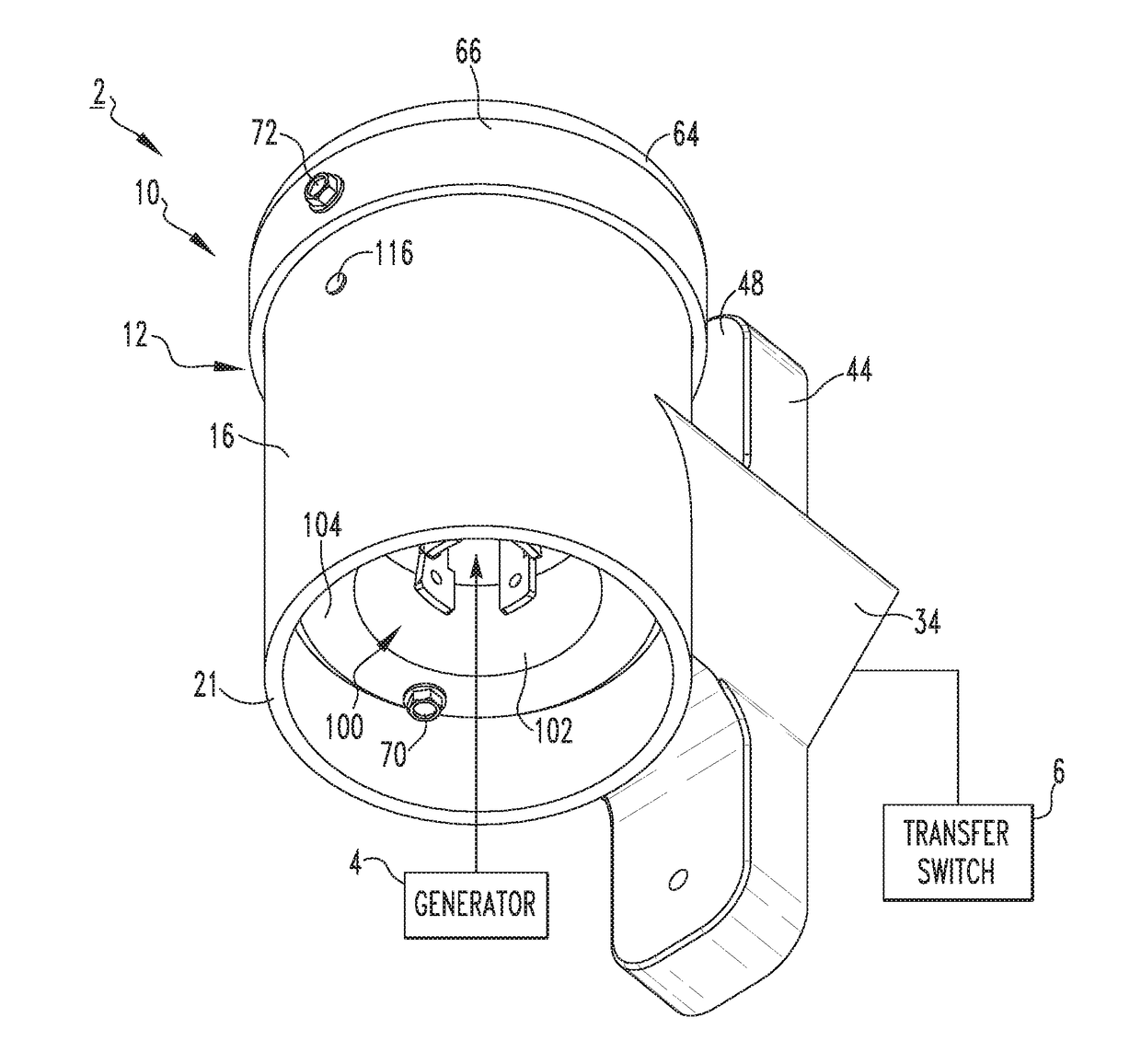
  • Electrical system, and power inlet apparatus and electrical receptacle assembly therefor
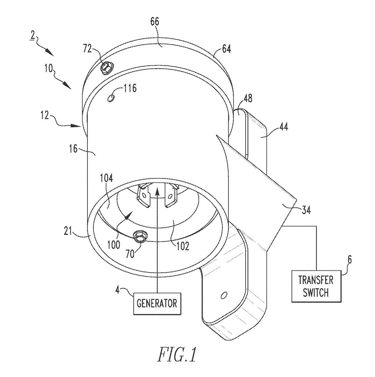
  • Electrical system, and power inlet apparatus and electrical receptacle assembly therefor
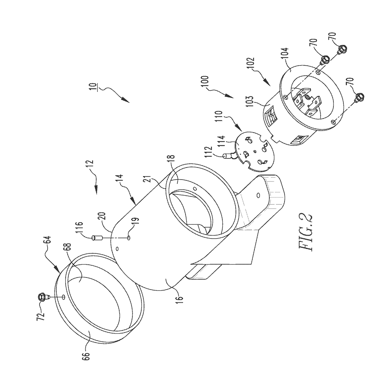
  • Electrical system, and power inlet apparatus and electrical receptacle assembly therefor

Examples


example

[0033]FIG. 8 shows an example circuit schematic 200 for an electrical system, in accordance with one non-limiting embodiment of the disclosed concept. As shown, the example circuit 200 includes a number of resistors R1,R2,R3,R4, a transistor T1, a zener diode ZD, a diode D1, a capacitor C1, and a number of status indicators (e.g., without limitation, light emitting diodes LED1,LED2) each having an ON condition (i.e., illuminated) and an OFF condition (i.e., non-illuminated). Resistor R1 has a first end connected to an Earth line and a second end connected to R2 and the gate of T1. R2 has a first end connected to the gate of T1 and a second end connected to the emitter of T1, the anode end of ZD, and a First Phase line. T1 has a collector connected to the cathode end of LED2 and an emitter connected to the anode end of ZD and the First Phase line. LED1 is electrically connected in parallel with D1. The cathode end of ZD is connected with the parallel combination of LED1 and D1. The a...


PUM


Abstract

An electrical receptacle assembly is for a power inlet apparatus of an electrical system. The power inlet apparatus includes a housing. The electrical system has a power source and a transfer switch. The electrical receptacle assembly includes an electrical receptacle structured to be mechanically coupled to the housing and electrically connected with the power source and the transfer switch, and an indication assembly mechanically coupled to and electrically connected with the electrical receptacle. The indication assembly has a status indicator adapted to provide an indication of circuit status within the electrical system.

Description

BACKGROUNDField[0001]The disclosed concept relates generally to electrical systems, such as, for example, electrical systems including generators. The disclosed concept further relates to power inlet apparatus for electrical systems. The disclosed concept further relates to electrical receptacle assemblies for power inlet apparatus.Background Information[0002]Electrical systems commonly include power inlet apparatus for providing an electrical pathway between a power source, such as a generator, and a transfer switch located inside a building, such as a residence. Power inlet apparatus, which include electrical receptacles, are typically mounted to the exterior of the building and provide an inlet for the supply of electrical power from the generator. The generator transfer switch is typically connected to the main electrical panel or load center of the building. The electrical receptacle of the power inlet apparatus is connected with a cord from the generator for providing power fr...

Claims


Application Information

Patent Timeline
Patent Type & Authority Applications(United States)
IPC IPC(8): H01R13/717H01R13/73H01R24/30H01R13/447H02J9/06
CPCH01R13/7175H01R13/7172H01R13/73H02J2009/068H01R13/447H02J9/061H01R2105/00H01R24/30H01R24/66H02J9/068
Inventor CLARK, JOHN THOMASCOURSON, ANDREW WILLIAM
Owner EATON INTELLIGENT POWER LTD
Learn More