
Multiple link connector list

a multi-link connector and connector technology, applied in the field of communication network management, can solve the problems of user inability to ‘point and click’ a desired connection, user inability to go to the location, and user inability to ‘point and click’ a connector, so as to improve the network view, improve the corrective action, and reduce the clutter of the map

Active Publication Date: 2005-10-20
ALCATEL LUCENT SAS
View PDF15 Cites 25 Cited by
  • Summary
  • Abstract
  • Description
  • Claims
  • Application Information

AI Technical Summary

Benefits of technology

[0011] According to still another aspect of the invention, a method of using a modified graphycal user interface (GUI) adapted to reduce the cluttering of icons on a map of interest is provided. The method comprises: a) whenever a network device is connected to more than one outside network device of a group of outside network devices external to the map, displaying an outside link connecting the network device with the group using an interactive multiple link connector icon; and b) selecting the multiple link connector icon on the map to obtain a multiple link connector list, displaying an interactive outside link widget associated with an interactive group identification widget for each group of outside network devices connected to the network device.
[0013] Advantageously, the invention enables the users to readily view the entire list of linkages of the NE's and groups displayed on a GUI map and their status. This feature becomes especially important as network nodes become highly interconnected. By automatically creating composite connectors, map clutter is significantly reduced, providing the user with a better view of the network and with the ability to take better and faster corrective actions.
[0014] The multiple link connector list according to the invention also enables a user to view the links going outside of the current map, or the corresponding network element group. This saves an operator time when navigating network maps. Furthermore, automatically creating composite connectors saves an operator the time and effort of manually reducing map clutter.

Problems solved by technology

Often, an NE or a group is the origin over 50 arrows, making the map very cluttered.
As a result, the users are not able to ‘point and click’ a desired connection for selecting it.
Connectors on network topology maps such as the map provided by Alcatel network management system 5620 NM are just a label, and clicking on such a connector does not allow users to go to the location displayed on the label.

Method used


Image

  • Multiple link connector list
  • Multiple link connector list
  • Multiple link connector list

Examples


Embodiment Construction

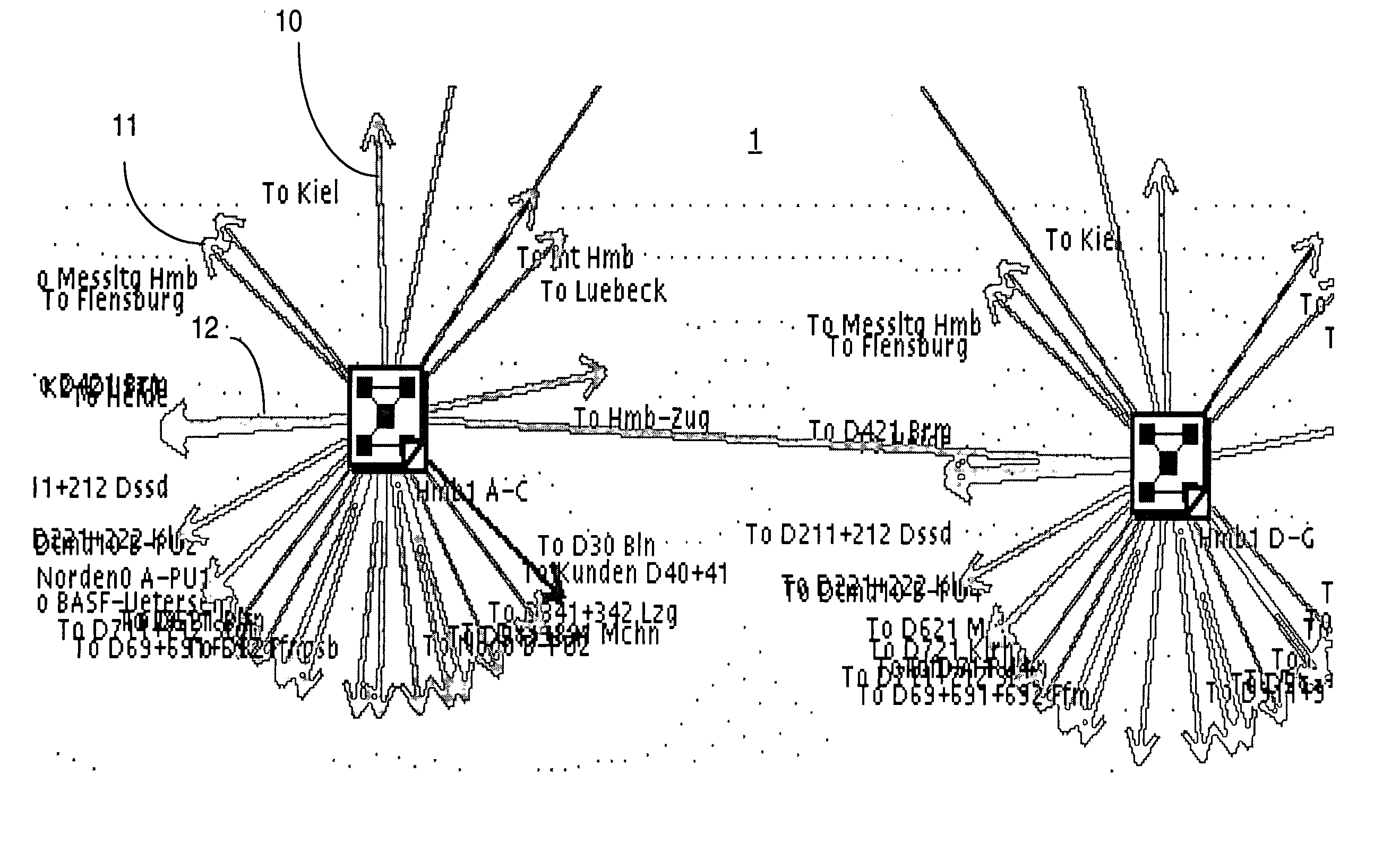
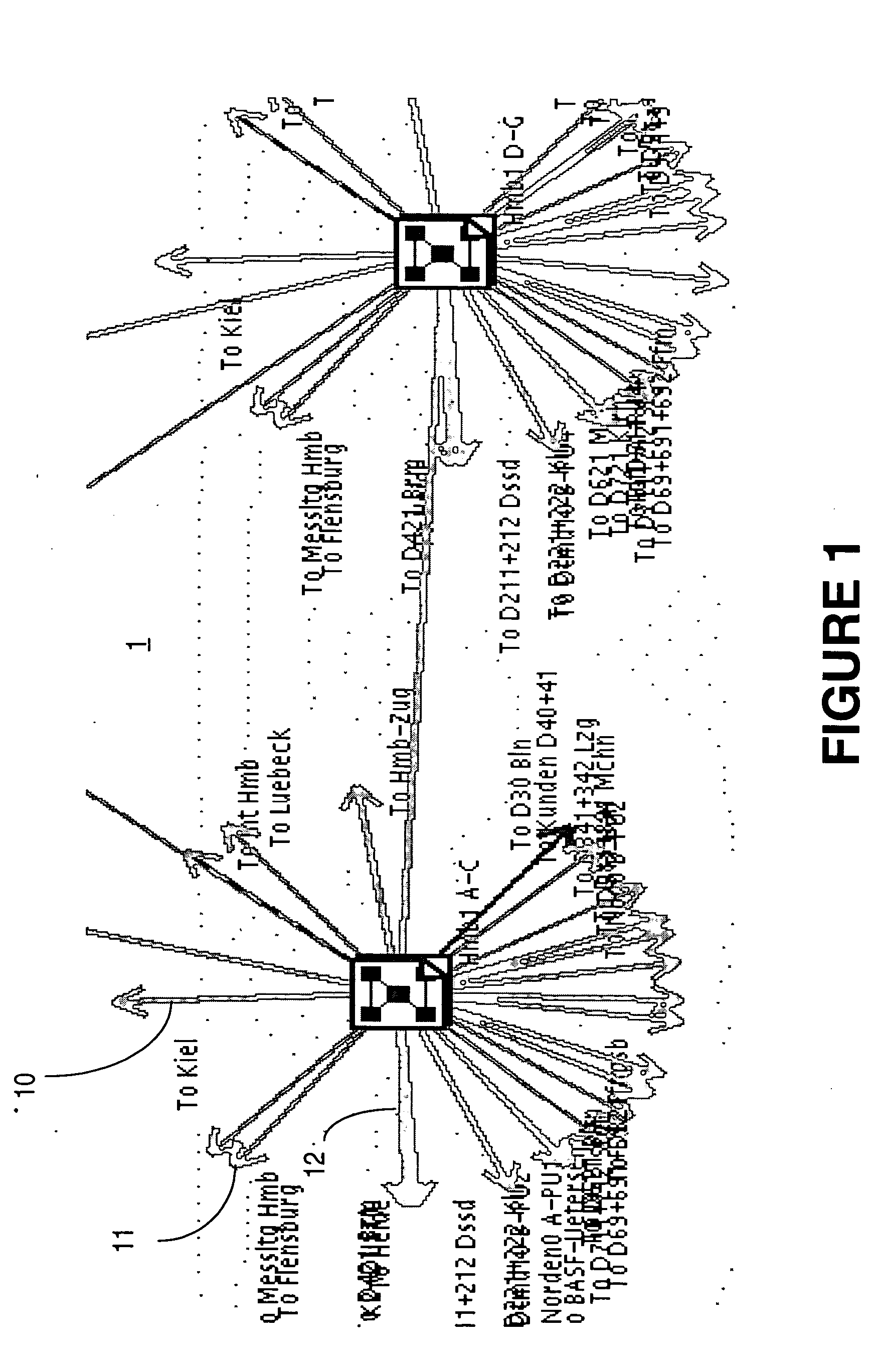
[0019]FIG. 1 illustrates an example of a GUI map 1 showing two network groups identified as “Hmb1 A-C” and “Hmb1 D-C”. Each device on map 1 is heavily connected to a plurality of network devices outside map 1. These links are shown by arrows.

[0020] Due to the large number of connections to outside NE's, most of the information about the links shown by arrows is useless, in that it cannot be readily read. Thus, while the identification of links such as links 10 and 11 is clear on map 1 (“to Kiel”, and “to Flensburg” respectively), the identification of link(s) as these shown at 12 is unclear. This is because there are two or more overlapping arrows, and correspondingly, two or more overlapping link identifications. As the operator cannot move the arrows, s / he cannot distinguish the link identification, and also s / he is not able to ‘point and click’ a desired connection for selecting one of the overlapping links.

[0021] In addition, the operator cannot access an NE that is outside th...


PUM


Abstract

A comprehensive network map for a graphical user interface (GUI) of a communication network, illustrates all outside links to network devices external to said map. To this end, the connections between a network device on the map and all groups of network devices outside of the map are illustrated using an interactive multiple link connector icon associated to the network device. The connector icon comprises a button for enabling display of a multiple link connector (MLC) list. Each row of the MLC list comprises an outside link widget associated with a group identification widget. A list with all connection between the network device and an associated group of outside network devices is displayed on the map upon selection of the outside link widget on the MLC list. Furthermore, a sub-map of a group is displayed upon selection of the respective group identification widget.

Description

FIELD OF THE INVENTION [0001] The invention is directed to management of communication networks and in particular to a multiple link connector list for display on the graphical user interface (GUI) of such networks. BACKGROUND OF THE INVENTION [0002] Modern management systems provide fully integrated network management for various technologies such as LAN, TDM, Frame Relay, ATM and IP, using a rich graphical user interface (GUI). A GUI (graphical user interface) uses object oriented programming techniques to present the information to the network operator for visual inspection, typically using interactive windows. The GUI selects the information to be presented in a window in accordance with a respective request in the context of network management and service provisioning capabilities of the network. The operators monitor and control the display of information on a video terminal (workstation) and the GUI enables the network management system (NMS) to receive, reject, accept and re...

Claims


Application Information

Patent Timeline
Patent Type & Authority Applications(United States)
IPC IPC(8): G06F3/00H04L12/24
CPCG06T11/206H04L41/22H04L41/0233
Inventor MARTINEAU, TERRENCEKIESEKAMP, DAVIDCANTON, RAYMOND
Owner ALCATEL LUCENT SAS
Learn More