Check patentability & draft patents in minutes with Patsnap Eureka AI!

Multi function fault circuit interrupter device and method

a fault circuit interrupter and multi-function technology, applied in emergency protective circuit arrangements, instruments, arrangements resposes to fault current, etc., can solve problems such as bimetal bends and eventually trips, circuit breaker must trip as quickly, and many devices consuming electricity from a single electrical circuit draw too much curren

Inactive Publication Date: 2018-11-01
EZ POWER LINES LTD
View PDF0 Cites 1 Cited by
  • Summary
  • Abstract
  • Description
  • Claims
  • Application Information

AI Technical Summary

Benefits of technology

The invention is a device that controls the distribution of electricity in a power grid. It uses low voltage to measure electrical properties between its output terminals and uses this information to connect or avoid connecting AC power to the terminals. The device can identify any load that is connected to the output terminals and determine if it is a living tissue or has ground-fault (when there is a short circuit in the ground).

Problems solved by technology

An overload results when many devices consuming electricity from a single electrical circuit draw too much current.
When the current exceeds the rating of the circuit breaker, the bimetal bends and eventually trips.
With short-circuit tripping, however, the circuit breaker must trip as quickly as possible.
The service life of the contacts of a circuit breaker is limited by the erosion of contact material due to arcing while interrupting the current.
Ground faults occur when electrical current is “leaking” somewhere outside of the path where the current is supposed to flow.
If human body provides the path to ground for this leakage, one could be burned, or even electrocuted.
Commonly used technologies for GFCI are outdated and therefore reacting to ground fault event too slowly or too late, after too much energy was able to pass through to the ground.
These are based upon loose induction coils that by their nature cannot provide fast readout of currents and not provide the high resolution required in order to improve their performances.
Commonly used overload circuit breakers are based upon bimetal automatic switches, and therefore require high amount of energy to heat up and bend and by that open the circuit.
They are expensive, slow reacting and cannot be configured for high resolution current sensing.

Method used


Image

  • Multi function fault circuit interrupter device and method
  • Multi function fault circuit interrupter device and method
  • Multi function fault circuit interrupter device and method

Examples


Embodiment Construction

[0013]In the following detailed description, numerous specific details are set forth in order to provide a thorough understanding of the invention. However, it will be understood by those skilled in the art that the present invention may be practiced without these specific details. In other instances, well-known methods, procedures, and components have not been described in detail so as not to obscure the present invention.

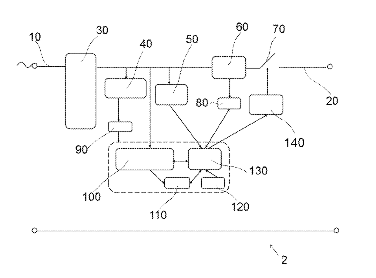
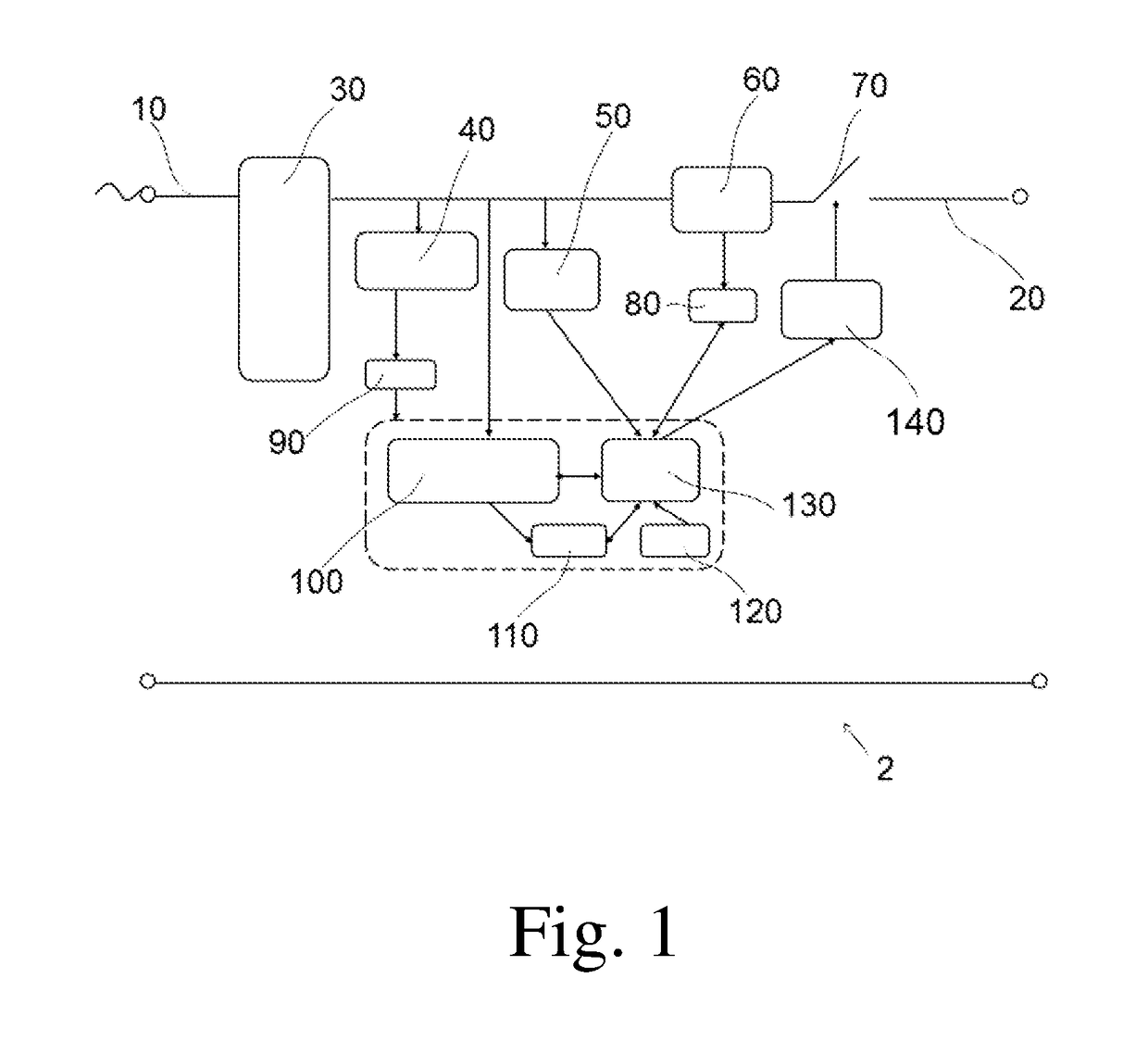
[0014]A fault circuit interrupter device configured, for electrically interconnect an electrical load to an electric grid is disclosed. The interrupter has an input terminal connectable to the electric grid and an output terminal connectable to the load. The interrupter device may comprises:[0015](a) a switch, optionally a normally open switch, between the electric grid and the load;[0016](b) a circuit configured for detecting a ground fault event;[0017](c) a circuit configured to detect an event of existence of live tissue connected between the output port termin...


PUM


Abstract

An interrupter device for controlling provision of grid power to its output terminals is adapted to sense, using low voltage, electrical parameters measurable between its output terminals and connect or avoiding connection of AC power to the output terminals based on the sensed parameters. The interrupter device is adapted to identify if any load is connected to the output terminals, whether that load is a living tissue, whether the load may pose too-high load or has ground-fault.

Description

BACKGROUND OF THE INVENTION[0001]A circuit breaker is an automatically operated electrical switch designed to protect an electrical circuit from damage caused by overload or short circuit. Its basic function is to detect a fault condition and interrupt current flow. Unlike a fuse, which operates once and then must be replaced, a circuit breaker can be reset (either manually or automatically) to resume normal operation. Circuit breakers are made in varying sizes, from small devices that protect an individual household appliance up to large switchgear designed to protect high voltage circuits feeding an entire city. The circuit breaker contacts must carry the load current without excessive heating. Contacts are made of copper or copper alloys, silver alloys and other highly conductive materials.[0002]A circuit breaker must detect a fault condition. An overload results when many devices consuming electricity from a single electrical circuit draw too much current. The circuit breaker pe...

Claims


Application Information

Patent Timeline
IPC IPC(8): H02H3/16G01R31/02H02H5/12G01R31/50
CPCH02H3/165G01R31/025H02H5/12H02H3/105G01R31/50
Inventor OFEK, ERAN
Owner EZ POWER LINES LTD
Features
  • R&D
  • Intellectual Property
  • Life Sciences
  • Materials
  • Tech Scout
  • Unparalleled Data Quality
  • Higher Quality Content
  • 60% Fewer Hallucinations
Learn More