Large angle flexible pivot

Pending Publication Date: 2018-11-08
ALMATECH SA
View PDF9 Cites 5 Cited by
  • Summary
  • Abstract
  • Description
  • Claims
  • Application Information

AI Technical Summary

Benefits of technology

[0011]A second advantage of the invention is that it makes it possible to determine independently the radial, axial, and rotational stiffness of the flexible pivot during the design phase. A third advantage of the invention is that the presence of the spokes and of the flexible connection means allows one to improve the centering of the axis, and thus to reduce the center shift drastically.
[0012]According to various particular embodiments of the invention, at least the first stage of the flexible pivot preferably comprises flexible attachment means for attaching the outer end of each of the flexible spokes in the set to either the first interface structure or the first cylinder (whichever one of the two surrounds the other one). One advantage of having flexible attachment means, is that it allows the effective length of the spokes to vary substantially. The flexible attachment means is preferably impleme

Problems solved by technology

Furthermore, this involves a very large number of cycles over the scanning range, on orbit.
Space mechanisms are also subjected to micro-vibration generated by the surrounding equipment.
The generation of wear particles is a problem for mechanisms in general and for optical applications in particular.
Indeed, wear particles can jam the mechanism and also migrate to optical components, thus directly affecting the optical performance of instruments.
While there are options for both wet and dry lubrication (specially developed oils and greases), these solutions have important drawbacks that are becoming more and more of an issue as both the lifetime and on-Earth storage time, increase.
Another drawback of conventional bearings is the n

Method used


Image

  • Large angle flexible pivot
  • Large angle flexible pivot
  • Large angle flexible pivot

Examples


Embodiment Construction

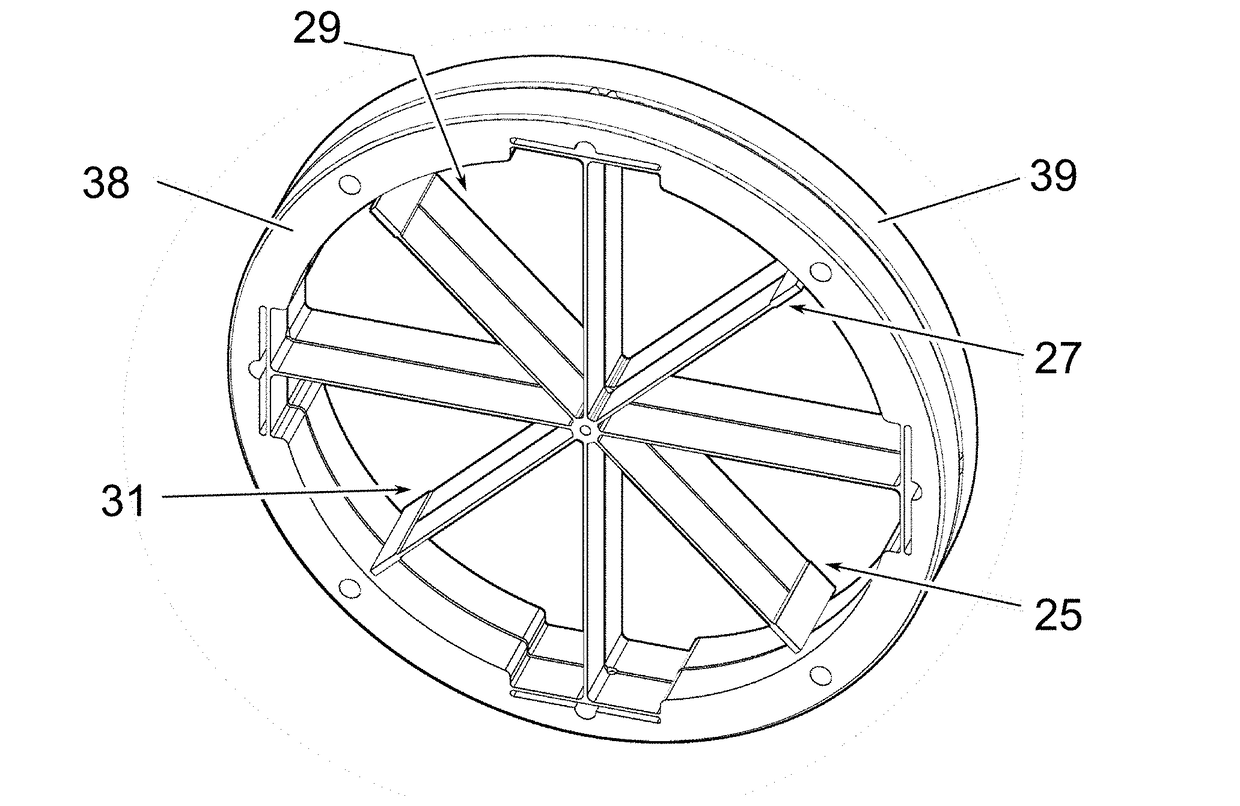
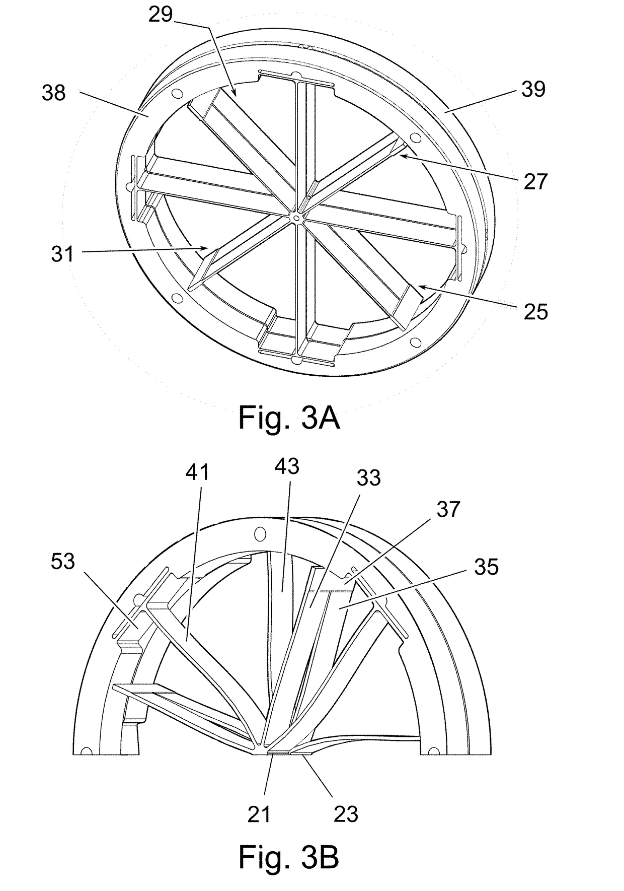
[0023]FIGS. 3A and 4A show two flexible pivots that correspond respectively to two particular variants of a first exemplary embodiment of the invention. The flexible pivots of the invention are preferably formed as an integral structure made from a single piece of material. For example, the material could be titanium or steel and the flexible pivot could be made out of a piece of metal by electro-erosion. The center of both the illustrated flexible pivots is formed by two hub portions in axial alignment with each other. Although the hub portions illustrated in FIG. 4A are not exactly cylindrical, all hub portions will be called cylinders in the following discussion. FIGS. 3A and 4A therefore both show a first cylinder 21, a second cylinder 23, and four flexible connecting members (referenced 25, 27, 29 and 31 respectively) for connecting the two cylinders. According to the particular variants illustrated in FIGS. 3A and 4A, the four flexible connecting members are regularly spaced a...


PUM


Abstract

A flexible pivot includes a first stage including a first cylinder and interface structure and a second stage including a second cylinder and interface structure in axial alignment with those of the first stage. Flexible connecting members are arranged for connecting the first and the second stages. Each flexible connecting member includes a pair of legs and a cross member joining the legs, each leg extending in a direction transverse to the axis of the cylinders, the legs being attached to the first and the second cylinders respectively. The first cylinder and the first interface structure are concentric. Flexible spokes are attached to the first cylinder by one end and to the first interface structure by the other. Each spoke extends in a direction transverse to the axis of the cylinders. Finally, the second stage includes flexible connection unit arranged to connect the second cylinder to the second interface structure.

Description

FIELD OF THE INVENTION[0001]The present invention relates generally to a flexible pivot comprising a first stage comprising a first interface structure and a second stage comprising a second interface structure in axial alignment with the first interface structure, the flexible pivot being arranged to be fixed to a base by one of the interface structures and to carry a load attached to the other interface, the flexible pivot comprising a first cylinder forming part of the first stage, a second cylinder in axial alignment with the first cylinder and forming part of the second stage, and a set of flexible connecting members for connecting the first and the second stages, each flexible connecting member comprising a pair of legs and a cross member joining the legs, each leg extending in a direction transverse to the axis of the cylinders, and the legs being attached to the first and the second cylinders respectively.BACKGROUND OF THE INVENTION[0002]Many space applications require activ...

Claims


Application Information

Patent Timeline
IPC IPC(8): B64G1/66F16C11/12B64G1/22
CPCB64G1/66F16C11/12B64G1/222F16C2326/47G04B31/00G04B17/045
Inventor BLECHA, LUCHUMPHRIES, MARTINPUYOL, YOEL
Owner ALMATECH SA
Why Eureka
Try Eureka