Friction testing apparatus and method
- Summary
- Abstract
- Description
- Claims
- Application Information
AI Technical Summary
Benefits of technology
Problems solved by technology
Method used
Image
Examples
Embodiment Construction
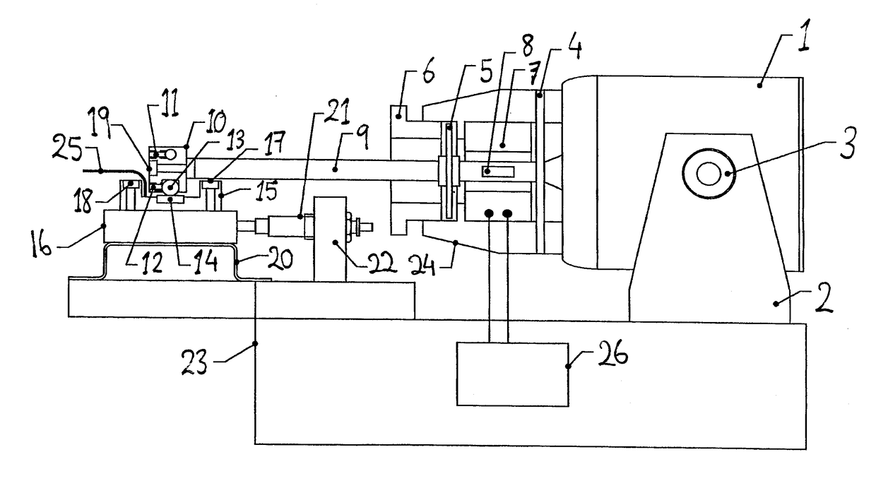
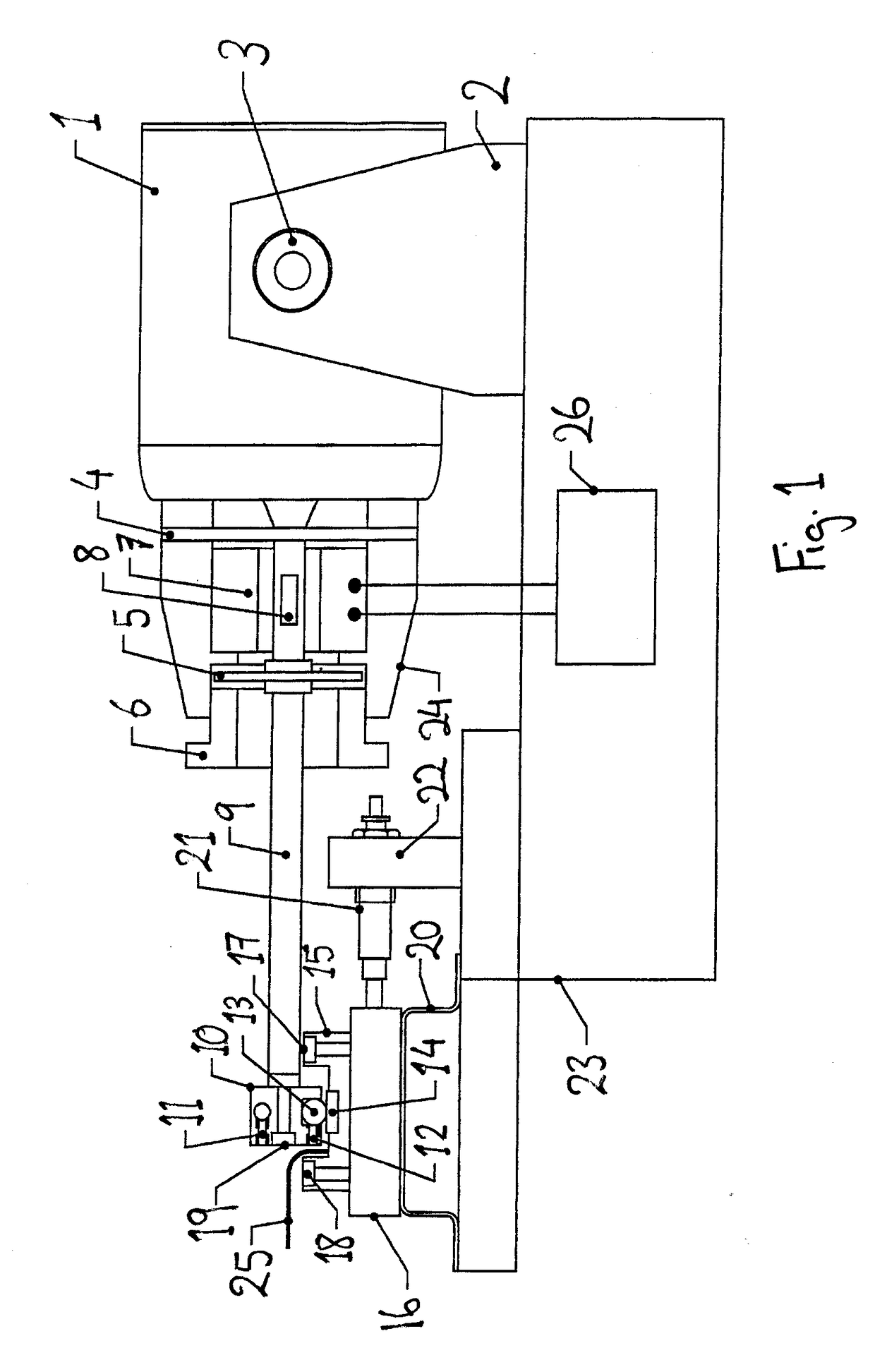
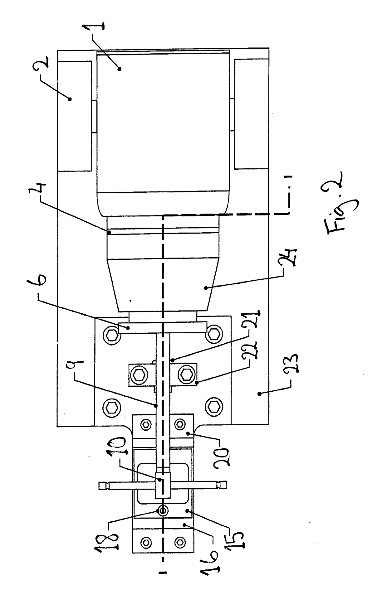
[0012]Referring to the drawings, there is shown one embodiment of a test apparatus according to the present invention having upper and lower specimens 13 and 14 respectively. The upper specimen 13 is releasedly held in the upper specimen holder 10 by a grub screw 12. The upper specimen 13 comprises a sphere of the material under test. The upper specimen holder 10 is releasedly attached by a screw 19 to a push rod 9 connected to the electromagnetic vibrator 1. The push rod 9 is in the form of a hollow tube of any suitable material with a measureable elasticity.
[0013]In this embodiment a rear flexure 4 is attached to the push rod 9 and clamped around its outside edge in housing 24. The rear flexure 4 acts to control the axial stiffness of the vibrator 1. A forward flexure 5 is designed to be about 10 times stiffer in the axial direction than the rear flexure 4 and is attached to the push rod 9 but free at its outside edge when operating at stroke lengths of more than 0.2 mm.
[0014]The ...
PUM
 Abstract
Description
Claims
Application Information
 - R&D
- Intellectual Property
- Life Sciences
- Materials
- Tech Scout
- Unparalleled Data Quality
- Higher Quality Content
- 60% Fewer Hallucinations
Browse by: Latest US Patents, China's latest patents, Technical Efficacy Thesaurus, Application Domain, Technology Topic, Popular Technical Reports.
© 2025 PatSnap. All rights reserved.Legal|Privacy policy|Modern Slavery Act Transparency Statement|Sitemap|About US| Contact US: help@patsnap.com


