Hip joint prosthesis friction wear testing machine

A friction and wear test, hip joint prosthesis technology, applied in the direction of testing wear resistance, etc., can solve the problems of difficult realization of equipment, test errors of hip joint prosthesis specimens, etc., to achieve accurate and objective test results, low cost, Control easy effects

Pending Publication Date: 2018-03-06
XUZHOU NORMAL UNIVERSITY
View PDF0 Cites 6 Cited by
  • Summary
  • Abstract
  • Description
  • Claims
  • Application Information

AI Technical Summary

Problems solved by technology

As far as the applicant knows, there are few domestic reports on the development of hip joint prosthesis friction and wear testing machines, and the existing hip joint prosthesis friction and wear testing machines are all open, affected by indoor temperature changes and hip joint prosthesis Due to the influence of frictional heat generated between the friction pairs, the ambient temperature during the test will change constantly, but the ambient temperature is an important parameter that affects the friction and wear characteristics of the hip joint prosthesis (the parameters that affect its friction and wear characteristics are: Material, load, temperature, motion form, etc.), so there are experimental errors in the hip joint prosthesis specimens obtained by the existing test equipment under the condition of changing ambient temperature
In addition, if you want to carry out the friction and wear test of the hip joint prosthesis under the same ambient temperature, different motion forms or different load conditions, it is also difficult to achieve with the current equipment

Method used


Image

  • Hip joint prosthesis friction wear testing machine
  • Hip joint prosthesis friction wear testing machine
  • Hip joint prosthesis friction wear testing machine

Examples


Embodiment Construction

[0021] In order to make the object, technical solution and advantages of the present invention clearer, the present invention will be described in detail below in conjunction with the accompanying drawings and specific embodiments.

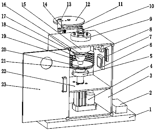
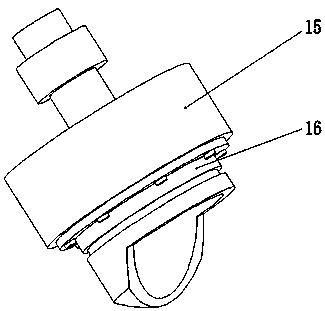
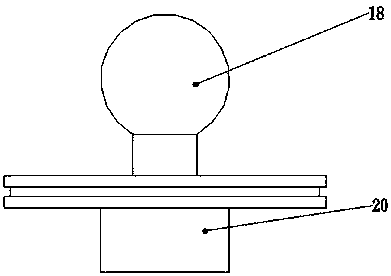
[0022] refer to Figure 1-Figure 4 , the hip joint prosthesis friction and wear testing machine provided in this embodiment includes a base 1 and a test box 3 installed on the base 1, and the test box 3 is divided into an upper cavity and a lower cavity by a box partition 22 Body, the servo electric cylinder 4 is installed in the lower chamber, the output shaft of the servo electric cylinder 4 passes through the through hole of the box partition 22 and is fixedly connected with the bottom end of the pressure sensor 5 arranged in the upper chamber, and the top end of the pressure sensor 5 is fixedly connected. Connect the lower test piece mounting seat 20, the top of the lower test piece mounting seat 20 is screwed to the joint head test piece 18; ...


PUM


Abstract

Hip joint prosthesis friction and wear testing machine, including a base and a test box installed on the base. The test box is divided into an upper cavity and a lower cavity by a box partition, and a servo electric cylinder is installed in the lower cavity. The output shaft of the cylinder passes through the through hole of the box partition and is fixedly connected to the bottom end of the pressure sensor arranged in the upper chamber, the top end of the pressure sensor is fixedly connected to the lower test piece mounting seat, and the top end of the lower test piece mounting seat is screwed to the joint The head specimen; the rear side of the test box is fixedly installed with a servo motor, the servo motor drives the crank rocker mechanism to drive the torque sensor to twist, the bottom of the torque sensor is connected with the top of the upper specimen mounting seat, and the bottom of the upper specimen mounting base The acetabular test piece is fixedly installed at the end; a sealing cover is provided between the upper test piece mounting seat and the lower test piece mounting seat; semiconductor cooling chips, heating resistors and thermocouple sensors are installed on the side of the upper cavity. The invention realizes the tribological test of the hip joint prosthesis at the set ambient temperature, and makes the test result more accurate.

Description

technical field [0001] The invention belongs to the technical field of medical machinery and equipment, and in particular relates to a friction and wear testing machine for a hip joint prosthesis. Background technique [0002] As a femur replacement technique, hip replacement is the most important method for the clinical treatment of severe osteoarthritis, joint tuberculosis and femoral head necrosis. Among them, the service life of artificial hip joint prosthesis materials in the body has always been the most concerned issue . Studies have shown that the hip prosthesis bears about 1 to 3 million cycles of body weight load in the body every year, and the service life is generally required to reach 10 to 20 years. The friction and wear between the joint head and the acetabulum is the main failure mode. In view of the complexity of in vivo tests, it has always been a research hotspot in the scientific community to study the wear resistance properties of hip prosthesis materia...

Claims


Application Information

Patent Timeline
Patent Type & Authority Applications(China)
IPC IPC(8): G01N3/56
CPCG01N3/56
Inventor 张嘉鹭王崧全杭文璐胡宁宁
Owner XUZHOU NORMAL UNIVERSITY
Why Eureka
Try Eureka